Yes, sure! You can buy a Sonoff RF and you are good to go, I guess. But I didn’t and I was not so sure about the no-named RF receiver so I ended thinking about adding my own.
But first things first. The Sonoff is an ESP8266 based smart switch by ITEAD which comes with a custom firmware that communicates with the manufacturer cloud to provide “smart” capabilities like remote switching or scheduling. The cool thing is that it has a line of pins that expose the VCC, GND, RX and TX pins of the ESP8266 and a buttons attached to GPIO0 so very soon it got hacked and there are a number of firmwares already available. I’m not an early adopter and some work has been done and reported by Peter Scargill, Javier or even in instructables.
The ITead Sonoff Smart WiFi Switch after a small hack to use the Avidsen RF remote to toggle it
About two months ago I bought 3 Sonoffs TH, the ones ready for mains switching but without RF receiver. When they arrived I reckon I tried ITead eWeLink App for Android but in less that 5 minutes I decided I had nothing to loose getting rid of it and flashing my own firmware.
Truth is that I’m living my own ESP-fever so I immediately plugged it to an FTDI adapter and tried a simple program. Goodbye eWeLink and guarantee voided (does it have any?). When I started figuring out what use could I give them I thought I could embbed them behind the switches in the wall but they are a dime too big and they use simple SPST relays, so no commuting (that’s a fail).
So next thing were lamps and other plugged appliances, starting with a warm lamp in the living room. But this particular lamp was already plugged to a RF switch and switched on/off from a remote. I realized I did not want to loose that. Having to unlock the phone to switch on the light sounded a bit weird. Why didn’t I bought the Sonoff RF instead?
Well, because I was not sure about the RF module it uses. How to handle it from custom code? Will my remote work with it (probably not) or will I have to buy theirs?
Time for a little hacking!
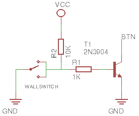
First step was to redo all the work I had already done when I started with these remote. It worked fine with Arduino but not with the Sonoff until I realize the 433MHz receiver I was using required 5V to operate. Mmm… No worries, even thou the ESP8266 works at 3V3 I remembered that in the schema for the Sonoff the AC/DC transformer feeds 5V to an LDO, so I could get the 5V from there.
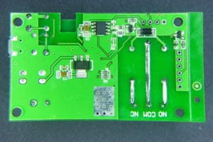
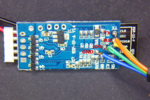
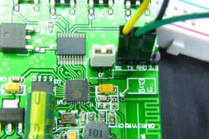
Back view of the Sonoff board with pin descriptions
Second problem was where to plug it. The answer was the line of holes where the RF module is in the Sonoff RF. Only two of those pins are tied to the ESP8266, the closest to the relay are GND and 3V3. Could I be so lucky? NO. The receiver I have (the standard RFLink you can find at ebay and such) has 4 pins: GND, DATA, DATA and VCC. Besides, the module just did not fit so close to the relay so the first pin would go in the second hole (the 3V3 hole)… OK, time for the X-Acto knife, the iron and the dremel.
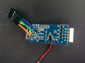
The RF receiver. I removed the black plastic around the pins to solder it closer to the board, otherwise it won’t fit in the case.
First I cut the traces leading to the 3V3 pin in the RF row of holes (that’s the second hole counting from the relay). There are surface traces on both sides of the board, so I had to cut both and then bridge them together again. Then I soldered the module in the 2nd, 3rd, 4th and 5th holes. I brought GND from the 1st to the 2nd hole, I then connected the DATA pin to the GPIO14 in the perpendicular row of pins through a voltage divider to ground to lower the 5V from the module to 3V3. A 10K and 20K 0805 SMD resistors do the job, but it was really hard to solder them between the pins… Next I soldered the VCC pin of the RF module to a spot in the board I checked was connected to the 5V rail.
Check the cut just by the LDO, there is another one in the same spot in the other side of the board. But cutting those traces removes power from the ESP8266 so I had to wire it again (it’s the white wire in the right). The other white wire powers the RF module with 5V. You can also see the GND bridge between pins 1 and 2 in the top row and the voltage divider from the DATA line to the GPIO14 and GND pins.
But the maximum distance from the remote to the module was something in the 20cm… until I soldered a 17.3cm wire to the antena hole in the RF module (that 1/4 of a 433MHz wavelength). Now I can be 10 meters away, even with a wall in between and I can still switch it on. And before you say anything: yes, range should be better for a 433MHz module but it’s fine, after all I can still switch it on/off from Australia via the Internet.
ESPurna Firmware
There are some fine control firmwares out there for the ESP8266. Some of them are generic and let you manage the pins one by one, some of them are more specific for “smart switches” based on the Espressif chip. Most of them have MQTT and Web configuration. Some are small enough so you can flash them Over-the-Air to the 1Mbyte Sonoff. None of them (at least I haven’t found any) have RF capabilities.
So I decided to build my own. After all that’s fun. I’ve named it ESPurna (“espurna” means “spark” in catalan) and it features:
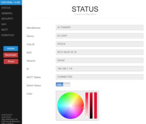
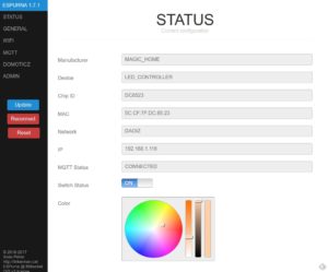
WebServer for configuration and simple relay toggle
Final step is to “wire” it all together. The Sonoff with the ESPurna firmware connects to my home WiFi and subscribes to a certain MQTT topic. Upon reception it switches on or off the relay depending on the message payload (0 for OFF, 1 for ON, 2 for TOGGLE). Whenever the relay state is changed it also publishes the new state to the same topic (there is code to avoid recursion). So if you change it manually pressing the button or with the RF remote you still have a record of that.
In my home server I have Node-RED running. A few months ago I switched from a bunch of python scripts to Node-RED for message persistence (in MySQL), notifications and to push data to some online services like Xively or TheThings.io.
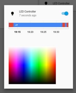
With MQTT and Node-RED working adding support for Blynk was a piece of cake. In 10 minutes I had a simple dashboard in my phone from where I could switch the lights on and off. In fact, I’ve spent way more time moving around controls in the dashboard canvas trying to make it look cool (I failed).
You know something is well designed when things fit in like magic.
Wow. I feel like I should explain many more things about this project, but there will be a follow up so stay tunedImage may be NSFW. Clik here to view.
Since I discovered the Sonoff I’ve been thinking about embedding it inside a switch. I started looking for old power meters, timers,… I had at home but the Sonoff is a bit too long. Why didn’t they design a square board? I event bought a bulky Kemo STG15 case with socket.
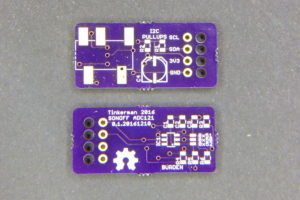
Next I decided to design my own board. It is meant to be the “official” hardware for the ESPurna project so it’s called ESPurna too. It’s opensource hardware and available at the ESPurna project repository at Bitbucket. I have some boards already for the first iteration (version 0.1). They are mostly OK but I’m already working on a revision.
But then ITead’s released their S20 Smart Socket. It’s the Sonoff in a wall socket enclosure. Almost 100% what I wanted. And at 11.70€ it’s hard to beat. There are other wifi smart sockets available, mainly Orvibo and BroadLink (an SP2 Centros should be arriving home anyday now) but ITead’s is cheaper and you can easily re-flash it. Just solder a 4 pins header, connect it to your FTDI programmer, hold the S20 button, connect the programmer to your computer and flash. Done.
OK, not so fast. Why would I do that? Why would I change the stock firmware?
The answer for me is a mixed up of philosophy and practicity. But you are right. Let’s go step by step.
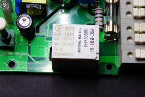
Hardware
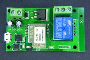
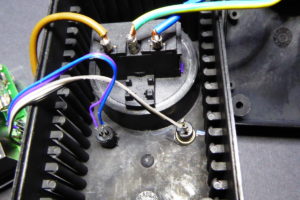
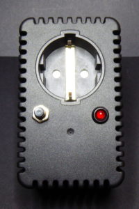
First let’s take a look at the device. The wall socket is nice looking and pretty small (at least compared to the STG15!!). In the socket you can read “16/250 ~” which I don’t know what it means since the relay inside is the same the Sonoff TH has and it’s rated at 10A and the label in the back says 2kW max, but maybe there will be a 16A version like the new Sonoff TH 16A. The ground terminals (connected from input to output) are not tightly fit and they make a metallic sound when you shake the device (OK, why should you shake it?). The ON/OFF button symbol is upside down (ehem). But the overall feeling is really good.
To take a look inside the enclosure you have to remove a single screw on the back of the device, but there is a “tore invalid” label covering it (hey, blame Google translate), so don’t do it.
A detail of the upside down button from the inside. It looks like a communication problem between the guy that was working on the enclosure and the guy that designed the button itself…
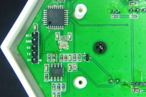
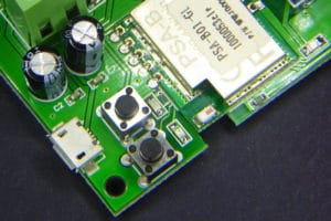
On the back of the board you can see the short live tracks, the ESP8266EX, SPI flash memory and the AMS1117-3V3.
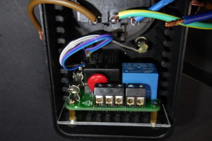
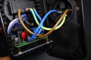
The guts of the S20 are very much like those of the Sonoff albeit with a different layout. Connections to mains are in the upper side, that provides a better isolation between the safe part and the unsafe part, whilst on the Sonoff you have hot tracks running all along the board. Like in the Sonoff it has live lines duplicated on both sides of the board and an extra of tin on the bottom. There are air gaps between the mains lines and the low voltage side, but they had to leave a bridge, probably to provide mechanical strength to the board.
On the bottom of the board you have several components including the ESP8266EX, a Winbond 25Q80DVSIG 8Mbit SPI Flash memory and an ASM1117-3V3 that provides regulated 3.3 volts to the ESP8266 and the flash chips from the 5V output of the AC/DC power supply. Whilst 1Mbyte on flash ROM is enough for most applications, even with OTA functionality (check my ESPurna firmware) some might find it a bit too short. If that’s your case there are cheap and easy ways to upgrade the memory chip to a 4Mbytes one.
There is a button attached to GPIO0 and two LEDs, a green one connected to GPIO13 like in the Sonoff and a blue one to the GPIO12, like the relay, so whenever the relay is closed the LED will lit blue. Close by the blue LED there is an unpopulated header perfectly labelled with VCC, RX, TX and GND lines. That’s everything you need to flash the ESP8266 onboard a custom firmware.
Software
ITead’s home automation products are managed through the eWeLink app for Android and iPhone. The goal of the app is to become a hub for different wifi home automation devices: switches, lamps, power strips, fans,… and the operation should be straight forward: set the device in pairing mode (AP mode), configure wifi credentials and control it.
I swear I have tried hard to use it. Several times. Even accepting weird permissions I would have not accepted to any other app (why should it ask for my phone number or my location?). But I never ever managed to make it work. I have not been able to pass the pairing step. Not even after giving the app permissions over my personal life. Impossible. I quitted. If anyone has a clue on how to do it, please let me know. Permissions and connection problems are common between the comments on Android app market. No one has commented yet on iTunes. Weird.
But even thou the app had worked fine I wouldn’t use it. I’m not saying you shouldn’t use it. My case might not be yours. Why would I flash my own firmware? Basically to really own the device.
We are in the very early days of the IoT and we are not even sure of what it means. Companies are trying to capitalize the concept providing their users all-in-one solutions including the device, the app and the cloud (whatever that is). But why should anyone know when you set your livingroom lights in romantic mode? And what happens if the company shuts off? Greenwave by TCP or Revolv cases are well know. Google has a reputed history of closed services (not IoT related, true).
And what about interoperatibility? You can easily end up having to use an app to switch your reading lamp and a different one for your ceiling light! Even those that provide open cloud solutions have weak days: Phillips recently released a trial balloon about locking out 3rd party hardware from Hue brigde. Elliot Williams at hackday put it simply: “The 900-pound gorilla in the corner of the Internet of Things (IoT) hype that everyone is trying to ignore is interoperability”.
That’s why i would always prefer open APIs and protocols over proprietary ones. I’m not even talking about open/free source software or hardware but protocols. You don’t own a device and the information it manages if you cannot talk to it directly, without middlemen.
The great thing about the Sonoff or the S20 Smart Socket is that you can easily flash your own firmware on them. So now I can control it with through my MQTT local broker, add schedules, behaviours,… through my local Node-RED instance or rely on 3rd party cloud services like Blynk or IFTTT if I want to, because if they ever shut off, it’s no big deal.
Conclusions
From the end-user point of view the device is a great deal: cheap, nice, wifi-enabled. But the mobile app is a disaster and I would expect people returning their devices because of this.
From the hacker point of view it’s a even greater deal. You can easily flash a custom firmware and make it talk to your local services. It could have more flash memory. It could have more GPIOs exposed in the header to add sensors like a simple LDR to switch ON/OFF depending on the ambient light or a PIR to detect that someone’s near. Or maybe it could have a jack out like the new Sonoff TH 10A/16A.
I will recommend the S20 Smart Socket to anyone with the skills to customize it. For less than 12€ it’s an amazing device you can own.
Have you ever forgotten your wet clothing inside the washer for a whole day? I have. Even for two days. They smell. You have to wash them again and you know you might end up forgetting about them again!
Actually that is happening to me since me moved to an old house in a town north of Barcelona. Instead of having the washer in the kitchen, like we used to, now we have it in the cellar, in a place I don’t normally pass by to notice the laundry is done.
So I started thinking about monitoring the washer to get notifications when the laundry is done. And since I was at the same time playing with ITead’s Sonoffs, which has an AC/DC transformer and a powerful controller with wifi, it looked like a nice project to put together.
EXTREME CAUTION: live mains are very dangerous. Don’t work with them unless you know what you are doing and what the consequences might be.
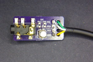
Wiring the ADC pin
The Sonoff does not bring out the ADC pin on then ESP8266EX. Some Sonoff TH versions do bring out GPIO14 and latest Sonoff TH 10A/16A probably do the same through a jack interface. But that’s not the case for TOUT aka ADC pin.
No problem, follow me: grab the iron with a narrow tip, a short thin cable and a magnifier, because you are going to need it. If you are not really good at soldering (and I’m not) you can still do it, but you will have to check and double check for bridges between the ADC pin and its neighbours. The ADC pin is the 6th in the left side of the chip (with the dot on the top left corner).
First solder a 3 pin header on the unpopulated holes for the RF module. If you use the first 3 counting from the relay you will already have GND and 3V3 on the first two, so you just need to connect the ADC pin in the Espressif chip to the third header. Take your time, do not apply heat for more than a second and leave it cool before doing it again. Check with your continuity tester after and prepare a simple gig to test your hack: a 10k potentiometer with a 20k resistor to build a voltage divider will do.
Update:
Don’t work with the board connected to mains! Again: Don’t work with the board connected to mains! After testing for shorts and continuity hot glue everything to prevent the cable from comming loose and create a potentially fatal short between mains.
That was tricky! Bringing out the ADC GPIO in the ES8266EX to a 3 pin header using the unpopulated RF header of the Sonoff…
Sensor board
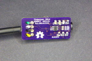
Now that I had the ADC pin I prepared a simple stripboard with a current sensor and a simple voltage bias circuit. The current sensor I use is a chep (and not very accurate) Talema ASM-010. It outputs a small voltage proportional to the current flowing through the hole. According to the charts in the datasheet the ratio is about 300A per 1V. That’s a very poor value, and even thou I could pass the cable twice, reducing the ratio to 150A per V the YHDC SCT-013-030, a very common non invasive current, has a ratio of 30A per 1V, 5 times more accurate. But I just need to know whether there is current flowing or not.
The board has two resistors (nominal 10k and 56k) to build a voltage divider to bias the output voltage by 0.5V so the ADC will always read positive values, and a 10uF capacitor to soften signal.
The Sonoff and the sensor board inside the enclosure.
Adapting the EmonLib
The EmonLib is the unofficial standard library to monitor current on an Arduino and alikes. But it doesn’t support ESP8266 based boards yet. Current issues are:
It only supports 10 bit ADCs (ESP8266 ADC is 10bits too, but it only has one analog pin, so chances are you will use an external ADC chip in some projects, like de 16bits ADS1115)
Voltage reference calculation doesn’t take into account non-atmel chips (the ESP8266 ADC is 1V referenced)
Analog reading is hardcoded in the library, again, what if you are using and external chip with I2C communication?
The usual approach is to include parts of the library code into your code and monitor analog pin 0. You could also use and external ADS1115 like Tisham Daar does.
This is not the first project I use current monitoring on a ESP8266, so I decided to wrap all the functionality I wanted in a proper library. And so EmonLiteESP was born. As the name says it’s a lite version of the EmonLib, since it only supports current monitoring at the time (only apparent power). But truth is that naming it after the EmonLib could be misleading since it is not API compatible (and maybe I’m violating some trade mark, didn’t check that).
The library main features are:
Customizable ADC bit count
Customizable ADC voltage reference
Read ADC values via callbacks
And its easy to use:
#include "EmonLiteESP.h"

EmonLiteESP power;

unsigned int adcBits = 10; // ADC bit resoltion (normally 10)
double referenceVoltage = 1.0; // 1.0V for a bare ESP8266 chip
double currentRatio = 30; // 30A 1V for a YHDC SCT-013-030
double mainsVoltage = 230.0 // EU standard
unsigned int samples = 1000; // 1000 samples each time we measure current

unsigned int currentCallback() {
   return analogRead(0);
}

void setup() {
   Serial.begin(115200);
   power.initCurrent(currentCallback, adcBits, referenceVoltage, currentRatio);
}

void loop() {
  double current = power.getCurrent(samples);
  Serial.print(F("Power now: "));
  Serial.print(int(current * mainsVoltage));
  Serial.println(F("W"));
  delay(5000);
}
Now that…
Some time ago, at a previous job, our CTO was very concerned about unnecessary code. He had a list of anti-patterns to identify bad practices when developing a new feature. The YANGNI (You Are Not Gonna Need It, meaning just code what you are going to use now) was his favourite one. Another favourite was the YAQUE (spanish for “Now that…”). Now that we are touching this code, why don’t we add this cool feature?
So breaking the YAQUE rule I added a DHT22 sensor because I could, and because we have moisture related problems in the cellar. The sensor is connected to the GPIO14 pin already available in the Sonoff board. I soldered a 10K SMD0805 resistor between the left-most 2 pins of the DHT22 (VCC and DATA) and drilled a hole in the case to place the sensor outside the box.
Another improvement was to add a case mounted momentary button on the enclosure, soldered to the onboard button, so I can manually switch the relay ON and OFF.
I have included all these features in my last ESPurna firmware version. Please check it out at espurna bitbucket repository.
Analyzing the data
So the goal of this project was to get a notification when my laundry is done. You don’t really need an accurate power measurement for that, only monitoring if there is current flowing or not and keeping track on how long has the washer been “quiet”.
First step is to see how the washer power profile looks like. It will probably depend on the washing program you are using but for the one we normally use for day-by-day laundry it looks like this:
So you can see the washer has been working for 27 minutes (from 11:27 to 11:54) with several quiet windows of no more than 2 minutes each. Please note this measurements have been taken every minute averaging 6 readings every 10 seconds. For this program it might be enough to check whether the washer has been quiet for the last, say, five minutes after seeing activity and then emit the notification.
Node-RED driven notifications
Final step is to set a notification when the laundry is done. I’ve been using Node-RED for some time now and I like having everything in one place in a flexible and structured way: notifications, database persistence, cloud service connections (xively, blynk, thethings.io, thigspeak…), schedulers,…
Now that I have an MQTT topic with the washer power consumption is pretty easy to write a javascript function that monitors it and sends a notification when the washer has been idle for five minutes after some significant activity. To implement that I built a 5 positions ring that stores whether there has been activity or not for the last 5 minutes or last 5 messages. It sets a flag when at least 3 of those messages contain non-zero values (that’s a significat activity). After that, when the buffer empties (5 minutes without activity) it sends the notification and clears the flag.
I’m sure the code will be much more clear than my explanation:
// Configuration
const WASHER_BUFFER = 5;

// Get current state
var washer_flag = flow.get('washer_flag') || 0;
var washer_sum = flow.get('washer_sum') || 0;
var washer_store = flow.get('washer_store') || Array(WASHER_BUFFER);
var washer_pointer = flow.get('washer_pointer') || 0;

// Update state
var current = parseInt(msg.payload) < 100 ? 0 : 1;
washer_sum = washer_sum - washer_store[washer_pointer] + current;
if (washer_sum < 0) washer_sum = 0;
washer_store[washer_pointer] = current;
washer_pointer = (washer_pointer + 1) % WASHER_BUFFER;
if (washer_sum > 2) washer_flag = 1;

node.status({
    fill: (washer_sum === 0) ? "red" : "green",
    shape: "dot",
    text: "Washer machine state: " + (washer_sum === 0 ? "idle" : "working")
});

// Notifications
if ((washer_flag === 1) && (washer_sum === 0)) {
    washer_flag = 0;
    msg.topic = "Washer";
    msg.payload = "Your laundry is done!!";
    msg.trigger = {
        'topic': '/trigger/washer/done',
        'payload': 1
    };
} else {
    msg = null;
}

// Store state
flow.set('washer_flag', washer_flag);
flow.set('washer_sum', washer_sum);
flow.set('washer_store', washer_store);
flow.set('washer_pointer', washer_pointer);

return msg;
The message is then passed to a subflow that sends it to Pushover service and also publishes it to the local MQTT broker.
Some 3 years ago I started building my own wireless sensor network at home. The technology I used at the moment has proven to be the right choice, mostly because it is flexible and modular.
MQTT is the keystone of the network. The publisher-subscriber pattern gives the flexibility to work on small, replaceable, simple components that can be attached or detached from the network at any moment. Over this time is has gone through some changes, like switching from a series of python daemons to Node-RED to manage persistence, notifications and reporting to several “cloud” services.
But MQTT talks TCP, which means you need some kind of translators for other “languages”. The picture below is from one of my firsts posts about my Home Monitoring System, and it shows some components I had working at the time.
All those gears in the image are those translators, sometimes called drivers, sometimes bridges, sometimes gateways. Most of them have been replaced by Node-RED nodes. But not all of them. This is the story of one of those gateways.
Moving from XBee to Monteino
I want you to focus on the “Xbee MQTT Client” in the previous image. XBees are fairly expensive, hard to configure but also pretty powerful and full featured. I could deploy battery powered end devices that run for months from a coin cell like my door sensor or backed by a solar panel like in my weatherstation.
A year ago I started playing with LowPowerLab’s Monteinos as a replacement for the XBee network. A Monteino is an ATMega328 with the Arduino bootloader and HopeRF RFM69 radio on board, everything running at 16MHz and 3.3V. It is a truly low power device and the guy behind LowPowerLab, Felix Rusu, along with the Monteino community have put together an awesome set of libraries to use them. RFM69 use the ISM 868MHz band (here in Europe) with a longer range than the 2.4GHz XBees (although the later have mesh capabilities).
But Monteinos, just like XBees, do not speak TCP. They speak their own language over a FSK modulated radio signal at 868MHz. So you need a gateway to translate messages back and forth the two networks. That’s it, an RFM69 to MQTT bridge.
My first approach a year ago was to copy the XBee gateway idea I was using at the time, basically an XBee in coordinator mode listening to packets from the nodes and forwarding them over serial port to a computer running a python daemon with the python-xbee library to decode API frames and map them to MQTT topics using the Mosquitto python library (before it was donated to the Eclipse Paho project). So I wrote a simple program adapted from Felix Rusu’s gateway.ino example running in a Monteino with an FTDI adapter (yes, there is a MonteinoUSB but I don’t have it) that passes messages over serial port to the computer that translates them to MQTT messages.
Standalone gateway
A Monteino with an FTDI adapter, passing data over serial in a custom protocol to a python script to translate them to MQTT… and back. I was not satisfied with the solution and I never finished the migration from XBee to Monteino.
But now I’ve done another step in what I feel like is a good solution. A standalone ESP8266-based gateway with an RFM69CW radio module on board. I’m not going to say this is the final solution, still have some doubts about it but I like it because it’s a microcontroller based solution, that does just that, bridging two different networks, without help from any other component.
Also I used RFM69CW footprint because it’s pin-compatible with the RFM12b, so in theory (I have not test it), you could make it work with old Monteinos or JeeNodes.
Non FTDI-like programming header. This was a hard decision but I had not very much free room and decided to bring out a GPIO instead, in case I wanted to attach some digital one-wire sensor.
Version 0.1 of the board has some errors, but still it’s usable. There was a fail in the ESP12 footprint I used, GPIO4 and GPIO5 were swapped. As a consequence DIO0 in the RFM69 module is tied to GPIO5 instead, nothing that could not be fixed changing a value in code. Also somehow I drew M2 holes in the board instead of M3 and the programming header is too close to the bottom-right hole so I have problems with common standoffs. And finally, there are problems with some of the silkscreen labels being too small (the button labels for instance) or missing (like the component values). This error has no impact on the functionality but I made it also on two other designs I sent to fab at the same time (ouch!).
Testing the gateway. The monteino in the picture has Rusu’s example gateway firmware, so I could check that nodes were sending well formed messages.
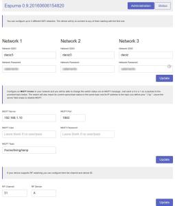
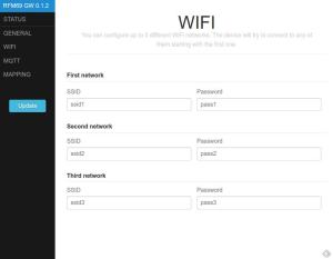
The project firmware packs some interesting features, IMHO. Let me summarize them first:
Up to 3 configurable WIFI networks
Over-The-Air firmware update (OTA)
MQTT support, off course
Dynamically map nodes/keys and MQTT topics
WebServer for configuration using the great PureCSS framework
Persistent configuration across reboots using Embedis
Optional default topic for non mapped nodes/keys.
Configurable IP and Heartbeat topics
Visual status of the received messages via the ESP12 LED
Topic mapping
As I explained in another post about MQTT topic naming I think the gateway should be the only responsible for translating messages from one network to another, and this means it has to have the logic to publish messages to the right MQTT topic, for instance. So I wanted to be able to dynamically define a map between nodes, variables and topics.
The gateway expects to receive messages with the key, the value and optionally the packetID (from the sender point of view) separated by colons (i.e. “BAT:2890:34″). This format is not the best in terms of size, but it’s compatible with Rusu’s MotionMote, for instance, and I had already used it in my XBee network. You can then map the combination of nodeID (available in the header of the message) and key to an MQTT topic.
You can also define a default topic that will be used when no match has been found in the map. The default topic can contain {nodeid} and {key} as placeholders to create custom on-the-fly MQTT topics.
Persistence
The other great feature is the configuration module. Just one word: Embedis. You have to use this library by PatternAgents. It’s basically a key-value database for microcontrollers that supports different platforms (including Arduino for AVRs and ESP8266) and different storage like SPI or I2C memories, EEPROM or emulated EEPROM like in the ESP8266. It’s easy to use, robust and powerful, and comes with console management with customizable commands as bonus feature.
Web configuration portal
Another aspect of previous projects I wanted to improve is the web configuration portal. I wanted to give PureCSS by Yahoo a try and it worked great, with jQuery as client language and ArduinoJson and Embedis in the backend. The layout is simple but looks great both on my laptop and on my phone and it’s much more usable than my previous efforts.
The JustWifi library supports up to 3 different networks. If it fails to connect to one of them it will try the next one.
Wifi & Radio management
Also, I have worked in encapsulating wifi and rmf69 functionality in two classes. The first one, JustWifi, is inspired by WifiManager but it just handles wifi connection (hence the name) ripping off all the webserver and DNS stuff. The second one, RFM69Manager, encapsulates the setup and receiving code and outputs a custom packet to the provided callback with all the useful information for a message (nodeID, key, value, packetID and rssi). It also wraps the send method to format a compatible message (“key:value:packetID”).
RFM69 and ESP8266
The moment I read this post in the LowPowerLabs forum I decided to do this project. Felix’s library for the RFM69 was compatible with the ESP8266 almost without modification! But the comments there were a bit confusing. So this is how I made it work:
Modify the SPIFlash.cpp file to check SPCR & SPSR before using. My solution is to wrap them between #if clauses to avoid compile errors if not defined, which happens in ESP8266. I’ve forked Felix’s library. Here you have the diff for the changes I made. UPDATE [2016-08-26]: I am no longer using this library for my ESP8266 firmware so this is not needed any more.
UPDATE [2016-08-26]:Modify RFM69.cpp file to change SPI clock divider to 2. In my tests this results in a great improvement when sending ACKs (or any other message). This is the patch you should apply on the file:
diff --git a/RFM69.cpp b/RFM69.cpp
index a1e1eeb..ad2e30b 100644
--- a/RFM69.cpp
+++ b/RFM69.cpp
@@ -450,7 +450,7 @@ void RFM69::select() {
   // set RFM69 SPI settings
   SPI.setDataMode(SPI_MODE0);
   SPI.setBitOrder(MSBFIRST);
-  SPI.setClockDivider(SPI_CLOCK_DIV4); // decided to slow down from DIV2 after SPI stalling in some instances, especially visible on mega1284p when RFM69 and FLASH chip both present
+  SPI.setClockDivider(SPI_CLOCK_DIV2); // speeding it up for the ESP8266
   digitalWrite(_slaveSelectPin, LOW);
 }
Initialize the RFM69_ATC object (or the RFM69, whichever you use) passing the SS and interrupt pins.
RFM69_ATC radio = RFM69_ATC(SPI_CS, IRQ_PIN, false, IRQ_NUM);
This is what the console output looks like. Messages are from a node that’s continuously sending the same payload. The node was powered after the gateway came to life, that’s why the first packetID is 1. You can also see how the RSSI value goes down. This is due to the Auto Transmission Control in the RFM69_ATC library that’s set to a minimum of -70. The transmitter will keep on lowering the output power to match this RSSI value, saving power and reducing radio pollution. Key “BAT” for node ID 10 is mapped to “/home/frontdoor/battery” topic (see screen capture above).
Funny enough, while waiting for the boards to arrive from a chinese factory, a couple of very similar projects have come to public attention, the Ebulobo by James Coxon and the Espism by Johan Kanflo.
Both boards are smaller than mine, basically because they place each module on one side of the PCB. They have both chosen to use an USB-A socket to power the board resembling an USB stick, while I use a 2.1mm barrel jack. The Ebulobo board has an SMA connector to plug an antenna, but the Espism uses a pigtail wire as antenna. My board has both options.
James’ Ebulobo uses a header to program it, very much like I do, but without power line (the board has to be plugged to a powered USB port) and instead of having a FLASH button on-board to pull GPIO0 down on boot, it brings out the GPIO0 in the header and you have to use a jumper to tie it to ground. Johan uses a custom programming connector (the Esprog) to flash the firmware on the Espism. This way he reduces board size but the payload is… that you need a custom programming connector.
Both projects have open sourced their schematics, board and code, so they are great projects to learn from. I like their form factor, not sure about the USB connector, not even if there was an FTDI chip and circuitry to program it like you would do to a NodeMCU. OTA is a better option in any case. If the reason is the ubiquity of a power supply connector a microUSB socket would be a better option.
Improvements
I’m just starting to deploy devices using this gateway. I guess I will find things to improve on the way. Right now, the main improvement I have in mind is to support sending messages from MQTT to a remote actuator with an RFM69 radio. Right now the gateway is only one-direction.
The problems I have identified in the board layout are fixed with version 0.3 in the repository, but since the board is fully usable I don’t plan to send it to fab. Yet.
I’m happy with the firmware, it’s a huge improvement from what I had been doing lately and I plan to migrate other projects like my Espurna Smart Socket firmware to use PureCSS and Embedis.
Again, any comment will be welcome.
Tinker and have fun!
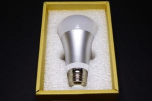
Some weeks ago I received a parcel from Itead. Previously, I had written about the Sonoff and they were kind enough to send me two more of their home automation products for me to review: the S20 Smart Socket I wrote about two weeks ago and the Slampher.
The Slampher comes in a simple cardboard box with no documentation at all… just visit their wiki!
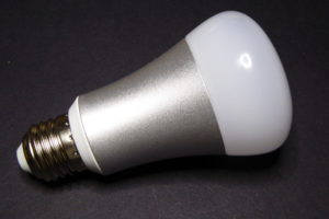
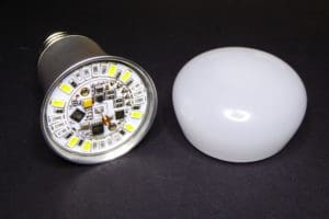
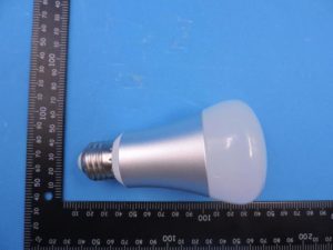
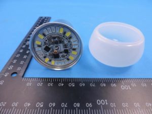
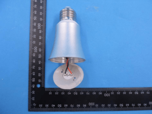
The Slampher is kind of a Sonoff RF that sits before any light bulb with an E27 screw. As you can see in the header pic of this post it adds quite some length to the group. It’s a bit bulky and might not fit in every lamp. Off course the board layout is different from the Sonoff and it uses a JST131U-800D 1A triac instead of a relay to switch the bulb. Aside from that they are equivalent.
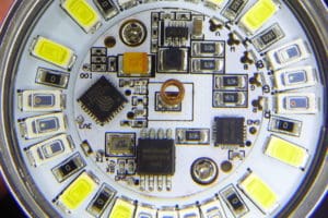
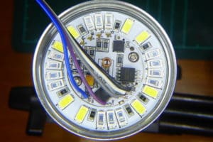
The JST131U-800D triac in a TO-92 package is placed in the the center of the board
There are a number of reviews of the Slampher that focus in the basic usage or that go more in depth tearing it apart or flashing a custom firmware. As you can guess, I’m more interested in the later. I already exposed my reasons in my post about the S20 Smart Socket and this week it has become more apparent as a report from Bitdefender has uncovered a bug on a commercially available smart socket that would allow attackers to create a malicious botnet. An army of owned sockets!
We are only a few days away from the arrival of the ESP32 and the ESP6288 is still one of the kings of the IoT block, and a really a successful one. Itead choice of using Espressif chips on their home automation line of products make them a hackers dream.
There are a few firmwares available that will work on the Slampher, including my Espurna Firmware. Most of them have MQTT support and a web configuration portal. Some, like the Espurna, are light enough to support OTA with the 1Mb flash memory that the Sonoff or the Slampher have.
Flashing the Slampher
The Slampher and the Sonoff RF both have a 8bit EFM8BB10F2G-A-QFN20 microcontroller (from the EFM8 Busy Bee family) by Silabs that listens to the radio module messages and handles the on-board button. That button is tied to GPIO0 in the Sonoff TH or the S20 Smart Socket and it can be used to enter into flash mode upon boot. Same things does not happen on the Slampher.
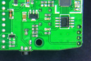
The EFM8BB1 is the little 3x3mm chip at the top right of the image, just by the testing pads.
The EFM8BB1 intercepts the button events so it can enter into “pairing mode” when the user double-clicks the button. In pairing mode it listens and stores a new radio code that will become the code to toggle on and off the switch from then on. But the curious thing is that if there is a single click event it just pulls down GPIO0 in the ESP8266 like the the button does in the non-RF versions. So Sonoff firmwares will work just the same except for:
You cannot use the button to enter flash mode in the ESP8266 (since it’s a user firmware event that pulls GPIO0 down and no user firmware is running at boot time).
You can’t use double click events on your firmware because these are intercepted by the EFM8BB1, unless they are more than about half a second away from each other.
You can’t use long click events since the EFM8BB1 pulls GPIO0 down only on button release for about 125ms.
Issues #2 and #3 you will have to live with them. My Espurna firmware uses double click and long click events to enter AP mode and to reset the board respectively. That will not work on the Slampher. I could extend the double click interval in the DebounceEvent library from 500ms to 1000ms, but it won’t be very user friendly.
Issue #1 has different solutions. Scargill suggests to move resistor R21 to R20, so the button is now attached to ESP8266 GPIO0 (check the schematic at Itead wiki). Problem is that you lose the ability to pair your remote. Off course you could pair it first and then move the resistor but chances are that in the long run you will need to pair it more often than flash it, because you have OTA.
So my solution is to momentarily shortcut to ground the unpopulated pad of R20 that goes to GPIO0 and power the device at the same time. It’s not easy, you will need some practice and you will probably have to do it more than once. But at the end you will have a customized Slampher with fully working RF support.
Short to ground the R20 pad that goes to the ESP8266 while powering the board to enter flash mode
Off course I’m assuming you have a stable OTA-able firmware and that you have a testing platform (I have a Sonoff just for that). Also, you can add a new button between the pad and GND to flash the device in a more comfortable way.
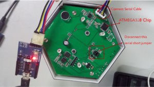
The Slampher has a 4 pins header that brings out everything you need to flash it (except for GPIO0), counting from the little white mark onwards: VCC, RX, TX and GND. You just need to wire your favourite USB to UART board (an FTDI-like) and you are ready to go. Just remember: the ESP8266 requires 3V3, not 5V! And connect TX to your programmer RX and RX to TX. Then you will need to handle the board with care with another ground jumper wire touching the R20 right pad (check the images) while you disconnect and connect you FTDI board or the VCC cable.
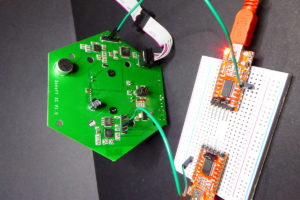
Somewhat hard to see but here you have my flashing set up… notice the additional black wire in the breadboard I use to pull down GPIO0 on boot
Radio codes
The radio receiver chip is a SYN470R by Synoxo in a 16 pin SOP package. This is a ASK/OOK RF transparent link (an “antenna-in to data-out” as the manufacturer says). It needs a microncontroller to act as a logic decoder. You can configure the bandwidth and it has a WAKEUP pin you can use to wake up your controller when there is a radio signal.
First I tried to pair it with my Avidsen remote without success. Then I used another remote I have for Noru radio sockets and it worked! Kind of… The red LED in the radio modules blinked while pairing it but not all the buttons worked. Only ON1, OFF2, OFF3 and 8H buttons on my Noru remote actually work with the Slampher. Weird.
So I reviewed my own post about decoding radio signals but instead of using my Bus Pirate I give it a try to the RCSwitch library first, using the basic receiver example and adding some code to output “normalized” data strings, I started decoding the 4 buttons of the remote Itead is selling. This is the code I used:
The output of the 4 buttons from the Itead remote is:
Button
Value
Binary
Tetrabits
A
11708433
101100101010100000010001
X10XXXX00F0F
B
11708434
101100101010100000010010
X10XXXX00F0X
C
11708436
101100101010100000010100
X10XXXX00FF0
D
11708440
101100101010100000011000
X10XXXX00FX0
As you can see they are 24 bit messages where the first 20 are the same for the 4 buttons and then there is only one bit set for the remaining 4 bits. The 4 buttons in the Noru remote that work have only 1 bit set in the last 4. That’s why the remote Itead sells has only 4 buttons. I still don’t know if I can use Itead’s remote with the Noru sockets since I never managed to know the relation between button codes (between ON and OFF buttons that control the same socket). But they don’t look compatible…
Note: one funny thing is that there is another EFM8BB1 microcontroller on the radio module. What? Maybe the radio decoding is done in this second chip while the one in the Slampher board is just responsible for the button and the GPIO0?
Wrapping up
The Slampher might be a bit bulky and it won’t fit in all the lamps (it does protrude from the livingroom lamp cover at home) but it’s a fine device for home automation. My criticism to the eWeLink app and my concerns about really owning the device still stand. But I will no doubt tell you: go buy one, flash it with your own firmware and enjoy.
Itead Studio keep on creating interesting products for the hacker community. A few weeks ago a new version of the already classic Sonoff TH came to life. This new version comes in two flavours: the Sonoff TH10 and TH16.
In this article I will briefly talk about what’s new in this device to quickly go to explore one of those novelties: it’s external interface.
What’s new?
The first thing I noticed is it’s size. The new Sonoff TH10 (or TH16, they are the same except for the relay) It’s a lot bigger than the old Sonoff TH. The old case is 87.5×38.8×23.5mm while the new one is 114×51.6×32.2mm. It’s bigger in every dimension and it they were cubes (they are not) the new Sonoff would be 2.37 times bigger in volume!!
“Classic” Sonoff TH (right) versus the new Sonoff TH10 (left). Does size matter?
Maybe we can find an explanation for this growth in the inside but my first though is that one of the good things about the Sonoff was it’s relatively small size (compared to it’s competitor by Electrodragon, for instance).
In the inside we have a completely different PCB layout. The PCB is also 1.82 times bigger (64.8×33.9mm versus 88.9x45mm) but it certainly breathes. Having all the connectors on the same side reduces trace distance and improves the separation between high and low voltage sides of the board. High voltage traces are a lot thicker and also have an extra of tin on top. All in all it looks like they have tried to answer people concerns about the safety of the device. But they still don’t have the CE mark (actually the CE mark in the case means “China Export”, check for the right Conformité Européene mark).
UPDATE 2016/10/08: Itead has contacted me to say that they are working on the CE certification and they expect to have it in no more than a month.
UPDATE 2016/10/20: Itead has contacted me again to communicate that some of their Sonoff line has now officially the CE certification (document of the CE certificate for new Sonoff products). The certification covers Sonoff TH10 and TH16 and also Sonoff DUAL and POW. They have also been certified as RoHS compliant.
The only difference between the Sonoff TH10 and TH16 is the relay. The TH10 uses a Hui Ke HK3FF-DC5V-SHG subminiature high power relay rated 10A while the TH16 uses a Honfa HF152F-005-1HTQ(104). The old Sonoff TH uses a HKE HRS3FNH-S-DC5V-A. They are all driven with GPIO12 through a transistor labeled 12W59. Don’t know enough about relays to know which one is better and why, what I know that none of them is a SPDT relay actually the Hul Ke is a SPDT relay, but the NC pole is not exposed and connected to the input line…. So crossover switching is still not possible…
Then there are these new push terminals. I guess they are easy to use while sticking the cable in the hole. Also the designers have added two neutral and two ground terminals so the user does not need a terminal bar to power the device and the load. There is also a very welcome F20AL250V 20A fuse.
The new push terminals and the fuse in the Sonoff TH10
The user interface has also improved with a new LED that can be driven with GPIO13 (the other one is tied to GPIO12, so it follows the relay state). The enclosure is thin enough so the LEDs are visible through it. Also the new button is much better in terms of usability and aesthetic pleasure. And finally there is the new external interface… which I will explore in the next sections.
The new interface
Using an audio jack as an interface is quite common. I used it in my Smartmeter pulse counter years ago. It’s also good news for anyone willing to add their own sensors. But it has two caveats: first they have decided to go for a 2.5mm jack, which is not as common as the 3.5mm one. Harder to find and more expensive. Second, even thou they are using a 4 channels jack (or TRRS for tip-ring-ring-sleeve) they are only using 3 of them for 3V3, GND and GPIO14. So what happened to the fourth?
Named pads, headers and test points in the Sonoff TH10 board
Well as you can see in the image the engineering team at Itead Studio actually thought about it. Only it’s not enabled. In the image above you can see that GPIO14 is tied to the jack tip with a 0Ohm resitor and a 5KOhm pull-up (actually two 10k in parallel). Side by side to this 0Ohm resistor there is a pad ready to connect the first ring in the jack to GPIO4 and another one to add a pull-up too. So you just have to solder a 0Ohm SMD resistor to that pad (the one with the GPIO4 label) to bring out a second IO to connect the sensor…
I don’t have 0603 SMD parts (too small for me) but a 0805 resistor fits just fine.
Have you read pull-up resistors? Me too. Do you know any 2 wire protocol that needs pull-ups? Me too!! So now we have a whole bunch of digital sensors we can attach to the Sonoff TH10/TH16.
A zillion of sensors, actuators, displays…
Itead Studio sells two sensors for the Sonoff TH10/TH16: an AMD2301 temperature and humidity sensor (DHT22 compatible) and a DS18B20 waterproof temperature sensor.
But now we can connect any digital device that requires one or two GPIO pins to drive it. And that includes I2C devices. We still have a limitation: the interface has a 3V3 channel, so we won’t be able to power 5V sensors with it… unless we hack that too (cut that thick trace going to the “3V3 / SLEEVE” point and solder a wire to any of the 5V test points in the image).
First I worked my testing cable. A 2.5mm TRRS jack to 4-channels Dupont connector.
So let’s start playing! A BMP085 pressure sensor, a HC-SR04 ultrasonic range module, a PIR, an I2C LED display or an nice little 0.96″ I2C OLED display…
What else… well, almost anything digital out there: displays, humidity sensors, distance sensors, touch sensors, encoders, magnetometers, gyroscopes, accelerometers, tilt switches, reed switches, real time clocks,… and also servos, external relays, buzzers, and WS2812 strips!
Last note before letting you go to find something to attach to your new Sonoff TH10/TH16. Tech people at Itead Studio know some of their clients will open the product enclosure and own the device by flashing their own firmware into it. They even use it as an advertising slogan: “For hackers, Sonoff Pow is another exciting board.”. So go ahead. The programming header is labelled and goes like this (check the picture above): VCC, RX, TX, GND. The button is tied to GPIO0 so just press it while powering the board and you are in flash mode.
If you don’t know what to flash give a try to the Espurna firmware. It’s a work in progress but will soon support I2C devices or two relays (for the Electrodragon or the Sonoff Dual) in different configuration modes including crossover switching.
By the way: I hope I will have a Sonoff Pow soon in my hands…
The HLW8012 is single phase energy monitor chip by the chinese manufacturer HLW Technology. It features RMS current, RMS voltage sampling and RMS active power with an internal clock and a PWM interface in a SOP-8 package. You can buy it at Aliexpress for less than a euro a piece and the necessary components are fairly easy to source and quite cheap.
All in all it looks like a great IC to include power monitoring in your projects. I guess that is why Itead Studio chose it for the Sonoff POW, one of their newest home automation products. And of course I have a POW here in my desk and I’ve been playing with it this weekend. The goal is to support it in my Espurna firmware but first I wanted to know more about the HLW8012. I’ll write about the Sonoff POW in a different post later this week.
HWL8012 basics
The HWL8012 is a 5V IC that monitors both voltage and current and output RMS voltage, current and active power encoded as a 50% duty cycle square wave where the frequency is proportional to the magnitude.
Current is measured by a differential potential measure across a milli-ohm copper-manganese resistor in series with the main current flow. The differential potential is fed into pins VIP and VIN. The resistor must be such than the wave in VIP-VIN peaks at 43.75mV maximum. A 1milliohm resistor is well suited to measure currents up to ~30A with a dissipation of less than 1W.
Voltage is measured in the same way but since the V2P pin supports up to 495mV RMS signals the potential has to be scaled down. The HLW8012 datasheet recommends a voltage divider of 6 470kOhm resitors upstream and a 1kOhm resistor downstream. That means a scale factor of 2821 that will convert a 230V RMS into 8mV that falls waaaay below the limit.
The product datasheet suggests the circuit below as a typical application and it’s the very same schematic you will find on the Sonoff POW (check it’s wiki page for a schematic). Except for the fact that the voltage divider in the Sonoff POW has only 5 470kOhm resistors.
On the MCU side of the IC we have two pins that output the square wave. The CF pin pulse frequency increases as the active power increases too. The relation depends on the reference voltage (2.43V), the internal clock frequency (3579kHz typically), the voltage divider in the V2P input and the milliohm resistor. For the suggested application in the datasheet a frequency of 1Hz corresponds to a ~12W active power, 10Hz to ~120W, 100Hz to ~1.2kW and so on.
The CF1 pulse is proportional to the RMS current or voltage, depending on the value in the SEL pin. If SEL is pulled high then the CF1 pin outputs a square wave with a frequency proportional to the RMS current measured. If SEL is pulled down it will ouput the RMS voltage instead. Nominal values (as per datasheet) are 15mA or 0.5V for a 1Hz wave.
A library for the HLW8012
The HLW8012 library for Arduino and ESP8266 is released as free open software and can be checked out at my HLW8012 repository on Bitbucket.
The library is still a work in progress as I still have to integrate it in a real project like adding support for the Sonoff POW to my Espurna firmware. So far I have tested stand-alone. The library (as of now) has two ways to monitor pulses: using Arduino “pulseIn” method or using interrupts.
The interrupt-driven approach is the recommended approach but requires you to wire the interrupts to the library. This is so because I didn’t want to do that from the library since that would mean creating a singleton instance of the library to be able to route the interrupts (at least, that’s the only way I know).
The bare minimum example would be:
(... definitions ...)

HLW8012 hlw8012;

void hlw8012_cf1_interrupt() {
    hlw8012.cf1_interrupt();
}

void hlw8012_cf_interrupt() {
    hlw8012.cf_interrupt();
}

void setup() {

    hlw8012.begin(CF_PIN, CF1_PIN, SEL_PIN, CURRENT_MODE, true);
    attachInterrupt(CF1_PIN, hlw8012_cf1_interrupt, CHANGE);
    attachInterrupt(CF_PIN, hlw8012_cf_interrupt, CHANGE);

    ( ... other setup code ...)

}

void loop() {

    static unsigned long last = millis();

    // This UPDATE_TIME should be at least twice the interrupt timeout (2 second by default)
    if ((millis() - last) > UPDATE_TIME) {

        last = millis();
        Serial.print("[HLW] Active Power (W)    : "); Serial.println(hlw8012.getActivePower());
        Serial.print("[HLW] Voltage (V)         : "); Serial.println(hlw8012.getVoltage());
        Serial.print("[HLW] Current (A)         : "); Serial.println(hlw8012.getCurrent());
        Serial.print("[HLW] Apparent Power (VA) : "); Serial.println(hlw8012.getApparentPower());
        Serial.print("[HLW] Power Factor (%)    : "); Serial.println((int) (100 * hlw8012.getPowerFactor()));
        Serial.println();

    }

    ( ... other loop code ... )

}
Please check the examples folder for more examples on how to use it all together, or use the non-interrupt approach.
Sensor calibration
Internally the library has 3 calibration factors that will apply to the pulse width reading. The actual magnitude (current, voltage or active power) is measured by dividing these values by the pulse width in microseconds.
The formulae are defined in the HLW8012 datasheet and, like I said, depend amongst other factors on the series resistor with the main line and the resistors that create the voltage divider in the V2P input. The library uses the recommended values for the typical application (also in the datasheet) but chances are your device uses a slightly different values of those, like using a 0.002 Ohm resistor instead of the 0.001 Ohm one. Besides, the real values and the nominal ones might not be 100% accurate.
The library provides two calibration methods to improve accuracy. The first calibration methods lets you specify the real values for the resistors around the HLW8012:
The second calibration method goes a step further and modifies the calibration values so the output matches the expected values for power, current or voltage. Of course if you use this second method the first one is not necessary. To calibrate the sensor using this method you will need some kind of interface to provide the expected values or start the device with a well know load.
The calibration load should be a pure resistive one or you can use an already calibrated commercially available wattimeter to read the values.
...
    // Calibrate using a 60W bulb (pure resistive) on a 230V line
    hlw8012.expectedActivePower(60.0);
    hlw8012.expectedVoltage(230.0);
    hlw8012.expectedCurrent(60.0 / 230.0);
...
The library does not remember the calibration values across reboots so you will have to implement some kind of persistence of your own. You can use the get*Multiplier() and set*Multiplier() methods to retrieve a manually set these values.
How does it work?
In the interrupt-driven approach, the library monitors the pulses in the background. When the code calls the getActivePower, getCurrent or getVoltage methods the last sampled value is returned. This value might be up to a few seconds old if they are very low values (a 6W LED lamp will output a ~0.5Hz square wave). This is specially obvious when switching off the load. The new value of 0W or 0mA is ideally represented by infinite-length pulses. That means that the interrupt is not triggered, the value does not get updated and it will only timeout after 2 seconds (configurable through the pulse_timeout parameter in the begin() method). During that time lapse the library will still return the last non-zero value.
On the other hand, when not using interrupts, you have to let some time for the pulses in CF1 to stabilise before reading the value. So after calling setMode or toggleMode leave 2 seconds minimum before calling the get methods. The get method for the mode currently active will measure the pulse width and return the corresponding value, the other one will return the cached value (or 0 if none).
Use non-interrupt approach and a low pulse_timeout (200ms) only if you are deploying a battery powered device and you care more about your device power consumption than about precision. But then you should know the HLW8012 takes about 3mA at 5V…
I’ve put together this library after doing a lot of tests with a Sonoff POW. The HLW8012 datasheet gives some information but I couldn’t find any about this issue in the CF1 line that requires some time for the pulse length to stabilise (apparently). Any help about that will be very welcome.
Some months ago I wrote about a hack I did to one of my Sonoff devices to be able to use a simple current sensor to monitor my washer machine process and alert me whenever my laundry was done.
A few weeks ago Itead Studio released two new models for their Sonoff line, the POW and the DUAL. And the POW is Itead’s answer to my hack. I’m not saying they copied me, just that the Sonoff POW makes my hack utterly unnecessary. Do you want to remotely monitor your devices energy consumption? Buy a POW.
What’s new?
Actually, the Sonoff POW layout shows some very significant differences to that of the Sonoff TH16, for instance.
Again, the Sonoff TH16 (left) and the Sonoff POW (right)
Obviously the POW has some circuitry for the power monitoring. The main component of this is the HLW8012 (the SOP8 packaged IC in the picture above). I wrote about the HLW8012 a few days ago, so I will not talk a lot about it here. The schema of the POW around the HLW8012 is almost the same as in the datasheet. You can see the 1 milliOhm manganese-copper resistor in the center of the board. The IC reads the difference in voltage at the edges of the resistor to calculate the current flowing through. Also, the 5 0603 470kOhm resistors left of the manganese one are the upstream side of the voltage divider that feeds the voltage monitor pin of the HLW8012.
A lot of components have been moved to new positions or removed. The HLW8012 sits exactly where the header for the RF module is in the TH16. So no chance for an RF+POW version. The diode bridge has been moved closer to the edge of the board and the creepage slots run deeper into the DC side of the board. The relay is almost exactly the same as in the TH16, a Honfa HF152F-005-1HST, also rated 16A@250VAC or 20A@125VAC. And the programming header sits in the same place.
Like the TH16 it has two LEDs, a red attached to GPIO14 like the relay (so it will be on whenever the realy is closed) and a green one on GPIO13. The button is, of course, tied to GPIO0 so you can use it to enter flash mode on boot.
But the most important difference from my point of view is that the Sonoff POW lacks the sensor interface I talked about in my post about the Sonoff TH10 and TH16. This is actually a pity. It’s like if Itead was teasing us with different options but forcing us to choose between a nice interface for external sensors or the power monitor feature. I will even add a third option to the list and it will make my perfect device, and hopefully next Itead release:
Power monitoring
External sensors
Socket enclosure (like the S20)
If they can sell that for under 15€ it’s a winner.
Quality of the new Sonoff line (TH10, TH16, POW and DUAL) is pretty good and that’s why they recently got the CE mark from the EU. The device looks solid, albeit a bit to big. The enclosure is the same as in the TH10 and 16. I still love how the button peeks out of the box. It almost looks like part of the enclosure.
ESPurned!
You can use the POW with the official eWeLink app. But if you have read me before you might already know I’m not going that way. Instead I soldered a 4 pin header and flashed my own firmware to the device. For the last days I’ve been mostly playing with the HLW8012. Check my post about the HLW8012 a few days ago for a deeper look into it and a library for ESP8266 and Arduino to use it.
Today I’ve been updating my ESPurna firmware with the HLW8012 library to support the Sonoff POW. It’s still under development but you can give it a try.
The ESPurna firmware is released as free open software and can be checked out at my Espurna repository on Bitbucket.
My daughters love to talk to (or with) my Amazon Dot in their funny English: “Alexa, hello!”, “Alexa, li-on!” (actually “light on”). It’s so easy to use it to switch on/off things at home using the fauxmo python script by Maker Musings. In his post about Amazon Echo and Home Automation more than a year ago he explains how he reverse-engineered the protocol of the WeMo switches that Alexa (Amazon Echo or Amazon Dot) supports.
I also have a server running the fauxmo script with an MQTT handler to control some of the Sonoffs I have at home, but this morning I woke up thinking: why should I use an external script to control my devices if I can code it in the firmware?
The fauxmoESP library
You will never be the first. Aruna Tennakoon had already done it a few months ago. But his approach did not suit me. I wanted something that could be easily embedded into an existing solution (like my ESPurna firmware). So I’ve coded it into a library I could include in my other projects and have it run in 3 lines of code. Literally.
Lately I have been migrating ESPurna to the state-of-the-art ESPAsyncWebServer by core developer Hristo Gochkov (@me-no-dev). So I decided to go for his suit of asynchronous TCP and UDP libraries for this project. The result is a fast, sturdy library that is amazingly easy to use.
The result is the fauxmoESP library, named after Musings’ code.
The fauxmoESP library for ESP8266 is released as free open software and can be checked out at my fauxmoESP repository on Bitbucket.
Installing and compiling it
Using PlatformIO
As I said, the fauxmoESP library depends on ESPAsyncTCP and ESPAsyncUDP libraries by Gochkov. You will need those first in order to compile it. You will also need the latest Arduino ESP8266 Core installation, at least from after July 11 2016. This is required to join the multicast group where the WeMo app (or Alexa) broadcast a message when searching for compatible devices.
Copy or checkout the ESPAsyncTCP and ESPAsyncUDP libraries in your arduino/libraries folder, it should be under “My Documents/Arduino/libraries” in Windows or “Documents/Arduino/libraries” in Mac or Linux unless you have placed it somewhere else.
Same for the fauxmoESP library, check it out in the arduino/libraries folder.
Restart your Arduino IDE
Look for the fauxmoESP_Basic example under File > Examples > fauxmoESP > …
Choose your board and compile.
Using it
Include the library, instantiate an object, set the device name define your devices and the message callback and you are done. It can’t be easier. Since all the networking stuff is asynchronous there is no need to manually poll for new messages. If you are using Amazon Echo or Dot, once the device is running click on “Discover devices” from the “Smart Home” tab and your device name will be added to the list, now just say “Alexa, turn on/off” and enjoy!
You can change the device name on the fly and re-scan for new devices, the old one will be replaced.
The latest version (1.0.0) allows you to define more than one device to be discovered and then perform different actions depending on which one was triggered. This was a suggestion by user Dave Myers in the comments below and has meant a change in the library API. The example below is taken from the 1.0.0 examples.As you can see the library requires a minimum setup.
#include <Arduino.h>
#include <ESP8266WiFi.h>
#include "fauxmoESP.h"
#include "credentials.h"

#define SERIAL_BAUDRATE                 115200

fauxmoESP fauxmo;

// -----------------------------------------------------------------------------
// Wifi
// -----------------------------------------------------------------------------

void wifiSetup() {

    // Set WIFI module to STA mode
    WiFi.mode(WIFI_STA);

    // Connect
    Serial.printf("[WIFI] Connecting to %s ", WIFI_SSID);
    WiFi.begin(WIFI_SSID, WIFI_PASS);

    // Wait
    while (WiFi.status() != WL_CONNECTED) {
        Serial.print(".");
        delay(100);
    }
    Serial.println();

    // Connected!
    Serial.printf("[WIFI] STATION Mode, SSID: %s, IP address: %s\n", WiFi.SSID().c_str(), WiFi.localIP().toString().c_str());

}

void setup() {

    // Init serial port and clean garbage
    Serial.begin(SERIAL_BAUDRATE);
    Serial.println();
    Serial.println();

    // Wifi
    wifiSetup();

    // Fauxmo
    fauxmo.addDevice("light one");
    fauxmo.addDevice("light two");
    fauxmo.onMessage([](const char * device_name, bool state) {
        Serial.printf("[MAIN] %s state: %s\n", device_name, state ? "ON" : "OFF");
    });

}

void loop() {}
Control your ESPurna device with Alexa
I’ve also worked on the integration of the fauxmoESP library in ESPurna. The code is there and it works but I have decided to disable support by default. Basically because of the required staging environment for the espressif8266 platform in PlatformIO.
Right now to compile it with WeMo emulation support you have to change the platform to “espressif8266_stage” and add “-DFAUXMO_ENABLED=1” to the build flags. Check my platformio.ini file above.
Once PlatformIO updates the espressif platform I will probably enable it by default.
November was a busy month and the Sonoff Dual that IteadStudio kindly sent me to review was bored in a box waiting for some free time. But it was just fair that another board that has been waiting in the boards-to-review box for longer had it’s chance to have some fresh air too. So here we have the Itead Studio Sonoff Dual and the Electrodragon ESP Relay Board face to face.
Face to face
They are both two relay boards with an Espressif ESP8266 controller. They are both powered from mains and programmable. The both have a similar size. They might look alike but they are actually quite different from the inside.
2x SONGLE SRD-05VDC-SL-C 125-250VAC 10A* (GPIO12 and GPIO13)
LEDs
Blue 3mm LED attached to GPIO13 and RG 3mm LED attached to relays (all of them visible from outside the shell)
SMD LEDs attached to the relays and to GPIO16 in inverse logic (none of them visible from outside the shell)
Buttons
1 available from the outside + 2 more in a header
2 surface buttons not accesible from the outside but also in the header
AC/DC
On board
As a module
Accessible ESP8266 GPIO
RX TX 3V3 GND
RX TX ADC GPIO4 GPIO15 3V3 5V GND and GPIO14 in the DHT22 footprint
* Please note that even thou the Electrodragon has 10A relays the board itself is no way able to handle such currents. The manufacturer recommends a maximum of 1A per line or 2A on a single line.
Those traces in the Electrodragon board are too thing for 10A
The Sonoff Dual is a more sturdy and end-user friendly device, it comes with a default firmware that connects to the eWeLink app for Android and iPhone and lets you manage the relays, configure schedules and much more. The Electrodragon on the other side is a hacker’s board, with a demo-firmware loaded which does very little.
Anyway I wanted to load my ESPurna firmware on both of them. It might look easy and for the Electrodragon is just a matter of adding support for multiple GPIO driven relays, but not for the Sonoff Dual.
IteadStudio Sonoff Dual
The Dual has 2 LEDs and one button meant to be used/checked from outside the enclosure. But the button is not connected to the ESP8266 (so you cannot use it to set the IC in flash mode, more about this later). The approach IteadStudio have used is pretty much the same they have in their PSB-04 modules: encapsulate the button and relay functionality in a helper microcontroller, a Silicon Labs F330. When a button is pressed the F330 reports the new status of the relays to the ESP8266 through serial. The ESP8266 can also change the relays statuses sending the proper commands to the F330.
The on-board button in the Sonoff Dual reports being button 2. Buttons 0 and 1 are available in a header properly labelled. The protocol has been reverse engineered by Markus Maeder and published in Itead’s support pages here. The messages have 4 bytes: starting byte, number of relays, status mask and stop byte.
Byte
Contents
Values
1
Start byte
0xA0
2
Number of relays
0x04
3
Status binary mask of the relays
0x00 to 0x0F
4
Stop byte
0xA1
So if the user presses the on board button (BUTTON2) the F330 will send 0xA00404A1 to the ESP8266 (provided everything was off). Bad news is that the communication is done through the hardware UART interface of the ESP8266 at 19230,8,N,1, so we cannot use it for debugging purposes.
Sonoff Dual support in ESPurna
The ESPurna firmware is released as free open software and can be checked out at my Espurna repository on Bitbucket.
I have added support for the Sonoff Dual to my ESPurna firmware. You can check it out in the repo but I’d like to highlight here the two chunks of code responsible for the communication between the ESP8266 and the F330.
The code above toggles the “id” relay (where “id” can be 0 or 1 for the Sonoff Dual) by xor-ing (what?) it in the “dualRelayStatus”, that is the variable that holds the status of the relays as a bit mask. This is from the ESP8266 to the F330. For the other way round we should check for the start and stop bytes:
void buttonLoop() {

    if (Serial.available() >= 4) {

        unsigned char value;
        if (Serial.read() == 0xA0) {
            if (Serial.read() == 0x04) {
                value = Serial.read();
                if (Serial.read() == 0xA1) {

                    // RELAYs and BUTTONs are synchonized in the SIL F330
                    // The on-board BUTTON2 should toggle RELAY0 value
                    // Since we are not passing back RELAY2 value
                    // (in the relayStatus method) it will only be present
                    // here if it has actually been pressed
                    if ((value & 4) == 4) value = value ^ 1;

                    // Otherwise check if any of the other two BUTTONs
                    // (in the header) has been pressent, but we should
                    // ensure that we only toggle one of them to avoid
                    // the synchronization going mad
                    // This loop is generic for any PSB-04 module
                    for (unsigned int i=0; i<relayCount(); i++) {

                        bool status = (value & (1 << i)) > 0;

                        // relayStatus returns true if the status has changed
                        if (relayStatus(i, status)) break;

                    }

                }
            }
        }

    }

}
Note some things in the code above. First we check for the message format (lines 23 to 26). Second we expect just one button to be pressed at a time so we break after a relay has changed it status (line 45). And third we intercept button2 presses and map them to button0 (line 33). So the external button toggles relay 0. Right now this is hardcoded, change it to “value = value ^ 2” to toggle relay 1 instead.
The relayStatus method does quite a few things: checks if the status has changed (returns true if so), sends the message back to the F330, synchronises other devices (more about it in a minute) and sends notifications to MQTT and websocket clients.
Flash the Sonoff Dual
Since the button is not connected to the ESP8266 GPIO0 flashing the Sonoff Dual is a bit trickier than doing the same on the TH or POW. My recommendation is to shortcut an exposed pad connected to GPIO for the first flash and then use OTA to upload the filesystem or update the firmware.
In the picture below you have a line pointing a resistor pad connected to GPIO0. Use a jumper cable to short it to ground while powering the board to get into flash mode.
The Electrodragon board is relatively simple to use. It’s a board meant for developers, not for end-users. The relays are directly connected to GPIO12 and GPIO13 so it’s just a matter of handling different GPIOs in the code. I use a vector to store all defined relay pins and then directly drive them with digitalWrite method.
To flash the Electrodragon note the pinout in the picture bellow. Power the device through the 5V pin. The RX marked pin should go to your programmer TX pin and the TX to the RX. Use the button labelled BTN2 to get into flashing mode. I’ve have better results holding it down while powering the board and until the firmware has started flashing.
If you have 2 relays you can control 2 appliances. Easy. But you can also do some other things like synchronising them. The ESPurna firmware supports 4 options:
No synchronisation
All off or at most one on (so if you turn one on all the other will go off)
One and only one on (so if you turn one on all the other will go off, but if you turn that one off again the next in the line will go on)
All the same (turn one on and all will go on, turn one off and all will go off)
Let me stop in the “one and only one on” since this this allows for multi-way switching, which is something I’ve been after since the first Sonoff.
This is a quite common way of switch where yo can toggle your lights from different switches in the room. A 3-way switch (like the one in the graphic) is usually implemented with a SPDT relay with exposed NO and NC terminals. But you can also use two relays with inverse sinchonisation, like the “one and only one on” mode does.
ESPurna 1.1.0
The ESPurna firmware is released as free open software and can be checked out at my Espurna repository on Bitbucket.
The firmware has been updated to support the Sonoff Dual and all the GPIO-based multi-relay boards out there, in particular the Electrodragon ESP Relay Board. This means a lot of changes:
MQTT topics for each relay (i.e. /test/dual/relay/0)
API entry points for each relay (i.e. PUT or GET /api/relay/0)
API entry point to get all relays (GET /relay)
Each relay is exposed as a different WeMo device
Different relay synchronisation options
I have also removed deprecated API entry points so all API requests go trough the /api namespace and require and API key.
I plan to add more API entry points to retrieve sensor values and a “pulse” mode for the relays so they can auto off after a second.
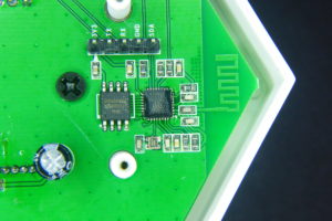
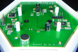
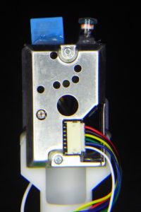
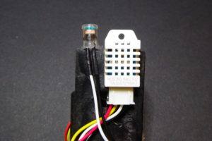
Last December Itead Studio updated their Home Automation product line with a new and different product. The main difference is that it doesn’t have a relay and it’s mainly sensors and no actuator (if we don’t define a notifying LED as an actuator). The Sonoff SC is a sensor station that packs a DHT11 temperature and humidity sensor, a GM55 LDR, an electret microphone with an amplifier circuit and a Sharp GP2Y1010AU0F dust sensor in a fancy case that looks like it was originally meant for a speaker.
The device is packs an ESP8266 as expected and is compatible with the eWeLink app. But, such a collection of sensors, with 3 of them having analog interfaces, cannot be run from the single-ADC ESP8266 so Itead has thrown in a good old ATMega328P to drive the sensors and report the Espressif with the data.
The outside
The first thing that draw your attention about the Sonoff SC is it’s casing. It’s kind of a truncated hexagonal-ish pyramid with a round grid on top and a rounded bottom. Seriously, somebody had a good time designing this. It looks a lot like a intricate speaker and actually that’s what it is. The reset/flash button sticks out shamelessly from a hole labelled “Audio” on one side of the enclosure.
Side by side with the fake audio hole there is an microUSB connector that’s only for powering the device (no data lines connected) and a microSD slot. The microSD reader is connected to the ATMega328P and I’m not sure what original purpose it has but I can think on a couple of good things to do with it.
On the bottom you have 4 black screws. Remove them to gain access to the insides of the device.
Once the 4 screws are removed it can still be a little tricky to take the PCB out from the enclosure since the button shaft leaves little room to lift the PCB from the plastic holders. Meanwhile you try to remove it, take a look at the components on that bottom side of the PCB. There you can find the controllers and programming headers.
The ATMega328P microcontroller with a 16MHz crystal. The SO-8 IC is a SGM358 dual op-amp used to amplify the electret signal. You can also see a header with 5V, TX, RX, GND and RST.
On the opposite site you have the ESP8266 IC with a Winbond 1Mbyte flash memory. You can see the PCB WiFi antena and the programming header with all the needed pins plus the SDA pin. The button is attached to GPIO0 so press it while powering the board to get into flash mode.
A perspective view fo the bottom side of the PCB. Three more things to note: the jumpers in the center-top of the image connect the RX and TX lines of the ESP8266 and the ATMega328P. Left of that, by the ATMega IC you have an unpopulated ISP header. You will have to solder a 2×3 header here to program the Atmel IC. Also, you have the Electret Mic in the forefront.
The other three sensors are pleaced on a plastic holder and fit inside the cone of the device. They are hot-glued between them and using standard JST connectors, so replacing them should be no problem…
Upgrading the Sonoff SC
There are a couple of simple, almost out-of-the-box, upgrades you can do to your Sonoff SC. First you can easily replace the DHT11 termperature and humidity sensor with a more precise DHT22 (AM2302) [Aliexpress]. Both sensors are pin compatible. You can read great full comparison of them plus the Sensirion SHT71. The DHT22 is better in accuracy and range to it’s cheaper sibling, but it also has a short life expectancy, so after all it’s a good idea to be able to replace it easily.
The DHT22 is also bigger than the DHT11. Make sure you place it so it does not protude further than the LDR capsule, otherwise you will have problems fitting everything inside the enclosure back again.
There is also an unused connector in the PCB meant for an LED. It’s driven by GPIO D7 in the ATMega328P through a 2N7002 mosfet in reverse logic (set to LOW to turn on). Remember you have an LED on the PCB as well driven by GPIO13 of the ESP8266 also in reverse logic. The 5V pin is connected directly to the USB supply, so if you have a good power supply you may as well connect here an WS2812 LED strip or ring for some colourful notifications. You will need a GND connection too but there are quite a few available (and properly labelled) on the board already.
The LED connector side by side to the dust sensor one.
New firmware for the Sonoff SC
This custom Sonoff SC firmware is released as free open software and can be checked out at my SonoffSC repository on Github.
So after making myself comfortable with the hardware of the device I started putting together some pieces grabbing code from other projects like the ESPurna firmware. The goal was to replace the code in the ATMega328 and the ESP8266 microcontrollers to be able to integrate the Sonoff SC into my home network. That means no cloud, that means MQTT.
While doing that I have added some features that came almost for free since I had already worked on them in other projects: Domoticz support for those that use that home automation platform and a “clap monitor“. Yes. Clap your hands to switch on/off the lights.
Just like the original firmware, this custom firmware monitors temperature, humidity, noise level (in %), dust (in mg/m3) and light (in %).
Communication
First thing was to be able to send messages between the ATMega328P and the ESP8266. Itead Studio provides a simple firmware for the ATMega328P in the Sonoff SC wifi page. The firmware is a good starting point but I don’t like it’s architectured. Everything is too coupled.
So first thing was to create a communications library between both microcontrollers. I started looking for similar solutions and found out the SerialComm library by fjctp. It was almost what I was looking for but I liked the AT commands approach, one char keys are too minimal and naming is important. So I wrote the SerialLink library that allows me to:
Compatible with AVR and ESP8266 ICs
Define custom commands (the library is agnostic) like AT+TEMP
Query command management (AT+TEMP=?)
Optional automatic ACK responses
Tolerant to noise in the line (debug output from the other controller)
Callbacks for get and set values from the application
Custom separator (=), terminator (\n) and query (?) chars
Currently, it only accepts integer payloads
In the picture below you have a sample of the communication between both microcontrollers. The ESP8266 debug messages are quite verbose but only those starting with AT+… are answered by the ATMegae328P. These are configuration messages “AT+EVERY=60” (set update interval to 60 seconds), “AT+CLAP=1” (enable clapping monitor) and “AT+PUSH=1” (enable message push from the ATMega328P to the ESP8266). Further down the log you start seeing MQTT messages due to push messages from the AVR about a clap code or sensor data.
The SerialLink library is currently bundled into my SonoffSC repository. I will create it’s own repo soon.
MQTT and Domoticz
MQTT and Domoticz integration was easy since most of the code was already there in the ESPurna firmware. I configured the communication link for push messages so in the ESP8266 side I have a callback function that gets all the messages from the ATMega328P and dispatches them to the different outputs.
In this code fragment you can see how message keys are matched and messages are forwarded to three different clients: MQTT, Domoticz and broadcasted to websocket clients like the web interface.
bool commsSet(char * key, int value) {

    char buffer[50];

    if (strcmp_P(key, at_code) == 0) {
        mqttSend(getSetting("mqttTopicClap", MQTT_CLAP_TOPIC).c_str(), value);
        return true;
    }

    if (strcmp_P(key, at_temp) == 0) {
        temperature = (float) value / 10;
        mqttSend(getSetting("mqttTopicTemp", MQTT_TEMPERATURE_TOPIC).c_str(), temperature);
        domoticzSend("dczIdxTemp", temperature);
        sprintf(buffer, "{\"sensorTemp\": %s}", String(temperature).c_str());
        wsSend(buffer);
        return true;
    }

    ...

}
Clap monitor
Now, this is more like a game feature. Don’t know if it’s really useful but it’s certainly fun to play with. Have you ever wanted to move someone by clapping your room lights into romantic mode? Well, this feature is about that.
The algorithm for clapping recognition is somewhat hard if you want to make it reliable, remove false positives and avoid “losing” messages. It’s not certainly suited for a noisy environments (I have kids at home…). My current approach is:
The ATMega samples the mic analog output (amplified) in 20ms windows and calculates peak-to-peak values
If peak-to-peak value is higher than a certain threshold during N consecutive time windows it flags it as a clap as remembers the current time in milliseconds
From the second clap on it stores the time between claps (there is also some debouncing code here)
After the last clap times out it checks if it has recorded any intervals (so that it has sensed a minimum of two claps in a row).
Clap intervals are coded into binary values. The value always starts with a 1 and each interval pushes a new bit from the right ad shifts everything up. The first interval length is considered a “short” or a 0. If an interval is at least 1.5 times bigger than the first one it is read as a “long” or a 1.
Finally the intervals array is reset and everything starts over again
This way I can encode clapping patterns as one byte codes. Two claps are always a “short” so it will be coded as b00000010 or 2. Three claps evenly spaced in time will be a b00000100 or 4. But if you leave a longer time (less than a second) between the second and third claps you get a b00000101 or 5.
I admit it’s somewhat weird but you easily get used to it. “Clap, clap,… clap, clap” (that’s a 10) and switch on the mirror light. “Clap, clap, clap, …. clap” (that’s an 9) and there goes the living room one.
Right now clapping codes are sent by MQTT to a user defined topic. So it’s a matter of having a service somewhere in you local network translating them to MQTT topics to perform different actions. This is a my test flow in Node-RED at home:
There are some features I’d like to add in the future. One thing is that the device has a microSD slot connected to the SPI lines of the ATMega328P. Log sensor data to an SD card could be an option here for non-connected mode.
Also I’d like to be able to map clap codes to MQTT topics, hence not needing an external service like NodeRED to do that.
A neat feature would be to be able to OTA flashing the ATMega328P form the ESP8266. It should be possible with a minimum hardware hack: wiring the RST pin in the ATMega328P header to the SDA (GPIO2) pin in the ESP8266 header to reset the AVR programatically.
Also, there are some spare GPIOs available in the board that could be used to add more sensors (the SPI header exposes 3 digital pins, but shared with the SD). Ideas?
Flashing the ESP8266
Flashing the ESP8266 is very easy since the header close to it has all the required connections (3V3, TX, RX, GND) and the button is connected to GPIO0. Press and hold the button while powering the board to set the ESP8266 into flashing mode. You will have to remove the TX jumper in the board to avoid the ATMega328P to interfere in the upload process.
My recommendation is to flash an OTA enabled firmware as soon as possible as use OTA from then on to update the ESP8266 firmware. This way you can keep the jumpers in place and debug the communications to the AVR IC.
Flashing the ATMega328P
The ATMega328P comes flashed with the Arduino bootloader so all you have to do is connect a USB to UART programmer [Aliexpress] to it and flash it from the Arduino IDE or PlatformIO. Notice that labels in the header are from the programmer point of view (weird). So wire RX to your programmer RX, TX to your programmer TX and RST to DTR. Use 5V logic. Also, you don’t want the ESP8266 interfere with the upload so remove the RX jumper that connects both microcontrollers. Actually remove both of them or the ESP8266 might complain with so much noise.
The ATMega328P comes with the Arduino bootloader so you can flash it using a USB to UART programmer (and FTDI-like). You will have to unbridge the connections to the ESP8266 to do it to avoid the ESP8266 interfere in the upload process. Photo by Itead Studio.
But, if you have an AVR programmer like the USBASP v2[Aliexpress] below, it might be a better option to program the ATMega328P using the unpopulated ISP header in the board. This way you won’t have to disconnect the jumpers between both controllers and have a stable test bed
The USBASP programmer I use to flash the firmware in the ATMega328P
Debugging
I’m using the ISP header to flash the ATMega328P and OTA to update the firmware in the ESP8266. This way I have everything connected and I can debug both microcontrollers using two USB to UART boards.
I use only RX lines connecting the RX of programmers to the RX pins in both headers (remember: RX to RX). Grounds are shared through my computer, but you might have to connect those too for better reliability.
Test and debug. ISP for uploading ATMega328P firmware, OTA for the ESP8266 and two RX llines to get debug messages from both microcontrollers.
Interface
The application web interface is stored in the ESP8266 using the same compression techniques I use for the ESPurna firmware. Right now you can:
Check the current values from the sensors
Configure up to 5 different WiFi networks (including the option for static IP)
Configure the MQTT connection and topics for the different sensor data
Configure the integration with Domoticz
Change the hostname (used for the DNS discovery feature: http://myhostname.local)
Change the sensor update interval
Enable/disable the clap monitor feature
The interface is based on jQuery and PureCSS. Here you have screenshots from the pages in the interface so you can get a better idea of what it can do at this moment.
Right now it’s a fully working firmware replacement for the Sonoff SC. You will maybe miss some features from the original firmware. Let me know which ones. Use Github (link below) to report issues or feature requests.
This custom Sonoff SC firmware is released as free open software and can be checked out at my SonoffSC repository on Github.
Lately I’ve been quite busy with the ESPurna firmware. It’s growing bigger and gaining some momentum. It’s really fulfilling to see other people using it and reporting back. But at the same time it’s very time consuming. Last Saturday I released version 1.5.0 with some new functionalities and bug fixes and I decided to use some of my free time over the weekend to work on a project that’s been waiting for a month in the shelf.
A few weeks ago I was playing with the Sonoff TH and I wrote a post about its sensor interface and the possibility of using lots of different digital sensors, including I2C sensors since the board can be easily hacked to export 2 digital pins over that interface.
And having I2C not only increases the number of potentially usable sensors but also opens the possibility of using I2C Analog to Digital converters to overpass the lack of analog inputs in the device. Here it comes the Texas Instruments ADC121 (datasheet), an 12-bit precision ADC with I2C support priced 2.74€ in quantities of 1.
Hacking the Sonoff TH
In my previous post about the Sonoff TH I already mentioned what to do to export a second GPIO in the 2.5mm jack output. It’s really simple, a 0Ohm resistor to bridge a pad (or a blob of solder) and a pull-up resistor if you plan to use it as I2C.
Two 0805 resistors (the noticeably bigger ones). A 0Ohm one to bridge the pad and connect the first ring to GPIO4 and the second one is a 5k1Ohm pull-up.
The think that puzzles me is that the pads for those 2 resistors are already there, but unpopulated. Obviously the engineers at Itead Studio designed a connector with 2 digital GPIOs but during the manufacturing it was decided to leave only one accessible. After all Itead is selling 2 sensors for the TH that both use just one digital pin, so I guess it was a money-driven decision, but still… it’s only two more resistors!
ADC121 board with connector for a 3.5mm CT jack
The idea was to have a small breakout board with an ADC and a more standard 3.5mm jack, the same size most of the non-invasive current clamps out there use. I decided to do a board with a single channel ADC121C027 by Texas Instruments.
The two sides of the Sonoff ADC121 board. It has pads for optional I2C pull-ups and a burden resistor in case your CT doesn’t have one already built-in. Also there is a pad to select the I2C address of the device.
The decision on what ADC to use was between the ADS1115 [Aliexpress, module] I already had experience with and the ADC121 family, specifically the ADC121C021 [Aliexpress] in VSSOP package and the ADC121C027 in SOT package. The ADS1115 has 4 16-bit ADC channels (or 2 differential) and 4 hardware selectable possible addresses. The ADC121 on the other side is a single channel 12-bit ADC with 3 possible I2C addresses. But they are half the price…
Since the goal was to create a current sensor compatible with the Sonoff TH and most of the times you would like to measure the current flowing through the same Sonoff, one channel is enough. Besides the I2C protocol allows to add multiple slaves to the same bus so there is always the possibility to stack different boards to connect different current clamps to the same Sonoff TH. Actually, modern houses here use to have 3 different power phases, so that seems a good number for the maximum number of addresses I could use in a single device.
So I decided to go for the cheaper ADC121 since it has 3 possible addresses and 12-bit ADC is enough for the measurements I want to do. I have a 30A/1V YHDC clamp and 12bit resolution over a 3.3V reference voltage means around 5-6W per unit (230V * 30A/V * 3.3V / 2^12 ~ 5.56W). Granted I will have some noise so it won’t be able to detect LED lamps or small home electronics like mobile charges and such, but it will be OK for traditional bulbs (yes, we still have them), heaters, washing/drying machines, fridges, microwaves,…
The board populated. The holes serve as strain relievers and they do their job very well. Also note there are no pull-ups in the board since the Sonoff TH already have them (in both lines now that I have added them)
On the bottom side there is the ADC121, some decoupling capacitors and the voltage bias (R5 and R6). Also the burden resistor is unpopulated since my current clamp has one built-in.
To solder the ADC121 I used solder paste and a hot gun. I’m still newbie using it but I’m improving. Actually, the hardest part was to know the right orientation for the IC. The footprint I had has a dot mark by pin #1, but the SOT6 I received has no dots anywhere, just an X31C label over a line running along the long side.
After investigating a bit I learnt that, usually, if you place the part so you can read the label the pin #1 is in the bottom-left of the IC. Good to know!
See the label? If you can read it (so it’s not upside down) the bottom-left pin is pin #1
EmonLiteESP with ADC121 support
The EmonLiteESP library is released as free open software and can be checked out at my EmonLiteESP repository on Bitbucket.
Once I had the board I wanted to write some code to test it. There are no ADC121 libraries out there, at least none the I have found. But the functionality I needed was so simple I decided to go straight to the code.
You might know that some time ago a wrote a simple power monitor library for the ESP8266 platform inspired in the EmonLib library for Arduino. The EmonLiteESP library does not implement all the functionality of the original library for Arduino and it’s not API compatible. It only monitors current, no voltage, so you can not get active power, only apparent power. But on the other side the reading is not tied to a specific analog GPIO. Instead you have to define a function callback that will return the analog reading using whatever sources you want, in particular using an I2C ADC.
It might sound complicated, but it’s not. The simplest function would be that returning the value from an analog pin:
unsigned int currentCallback() {
    return analogRead(CURRENT_PIN);
}
You will then pass this function to the library constructor so it knows how to get the reading. Much more flexible. Because now I want to get the value from an ADC121:
unsigned int currentCallback() {
unsigned int value;
// Ask for a reading
Wire.beginTransmission(ADC121_ADDRESS);
Wire.write(ADC121_REG_RESULT);
Wire.endTransmission();
// Get value (12 bits in 2 bytes)
Wire.requestFrom(ADC121_ADDRESS, 2);
if (Wire.available() &amp;amp;lt;= 2) {
value = (Wire.read() &amp;amp;amp; 0x0F) &amp;amp;lt;&amp;amp;lt; 8;
value |= Wire.read();
}
return value;
}
You see, the rest of the code does not change. This pattern is called the strategy pattern in books because it lets you define what strategy the library should use to execute a certain action, like getting an analog value.
Using the Brzo I2C library
The Wire library is part of the Arduino Core for ESP8266 and is API compatible with the Arduino library with the same name. But recently I knew about an implementation of the I2C protocol written in assembly (!!!) specifically for the ESP8266 platform by Pascal Kurtansky. The Brzo I2C library is open source and it’s available in the PlatformIO library manager.
What does it mean it’s written in assembly? Well, basically it means that it’s fast. How fast? A lot faster than the Wire library. In the EmonLiteESP repo you can find two examples for the ADC121, one using the Wire library and a second (adc121_fast) using Pascal’s implementation. Running the example using the Wire library with 1000 samples takes 544ms for each reading. The same with the Brzo I2C library takes only 85ms!! That’s 6.4 times faster!! Amazing. Actually you have to be sure you get at least one full period of the current wave. For a 50Hz system that’s 20ms. So 1000 samples are still 4 full periods.
The problem with the 544ms, aside from the obvious fact that it takes more time, is that 1) you get less samples per period, so your wave representation is very pixelated, so to say, and 2) you can get into problems with your wifi connection or other services that might need more attention.
Let me copy here the full example of the ADC121 using the Brzo I2C library. Some things to notice:
Same as with the Wire library for ESP8266 you can choose which two GPIOs to use as SDA and SCL. In the Arduino boards (in ATMega328 controllers) these are fixed in hardware.
The Brzo I2C library always uses buffers to send and receive data.
You have more fine grain control over the protocol, like SCL frequency and clock stretch time.
The current callback I talked about before is implemented here as a lambda function, that’s the “[]() -> unsigned int { …” stuff. There is no need to do it this way.
/*
EmonLiteESP ADC121 Example using Brzo I2C library
Energy Monitor Library for ESP8266 based on EmonLib
Currently only support current sensing
Copyright (C) 2017 by Xose Pérez &amp;amp;lt;xose dot perez at gmail dot com&amp;amp;gt;
This program is free software: you can redistribute it and/or modify
it under the terms of the GNU General Public License as published by
the Free Software Foundation, either version 3 of the License, or
(at your option) any later version.
This program is distributed in the hope that it will be useful,
but WITHOUT ANY WARRANTY; without even the implied warranty of
MERCHANTABILITY or FITNESS FOR A PARTICULAR PURPOSE. See the
GNU General Public License for more details.
You should have received a copy of the GNU General Public License
along with this program. If not, see &amp;amp;lt;http://www.gnu.org/licenses/&amp;amp;gt;.
*/
#include &amp;amp;lt;Arduino.h&amp;amp;gt;
#include "EmonLiteESP.h"
#include "brzo_i2c.h"
// -----------------------------------------------------------------------------
// Configuration
// -----------------------------------------------------------------------------
// I2C CONFIGURATION
#define I2C_SDA_PIN 4
#define I2C_SCL_PIN 14
#define I2C_CLOCK_STRETCH_TIME 200
#define I2C_SCL_FREQUENCY 1000
// ADC121 Address
#define ADC121_ADDRESS 0x50
// ADC121 Registers
#define ADC121_REG_RESULT 0x00
#define ADC121_REG_ALERT 0x01
#define ADC121_REG_CONFIG 0x02
#define ADC121_REG_LIMITL 0x03
#define ADC121_REG_LIMITH 0x04
#define ADC121_REG_HYST 0x05
#define ADC121_REG_CONVL 0x06
#define ADC121_REG_CONVH 0x07
// If you are using a nude ESP8266 board it will be 1.0V
// If using a NodeMCU there is a voltage divider in place, so use 3.3V instead.
#define REFERENCE_VOLTAGE 3.3
// Precision of the ADC measure in bits. Arduinos and ESP8266 use 10bits ADCs.
// The ADC121 is a 12bits ADC
#define ADC_BITS 12
// Number of decimal positions for the current output
#define CURRENT_PRECISION 2
// This is basically the volts per amper ratio of your current measurement sensor.
// If your sensor has a voltage output it will be written in the sensor enclosure,
// something like "30V 1A", otherwise it will depend on the burden resistor you are
// using.
#define CURRENT_RATIO 30
// This version of the library only calculate aparent power, so it asumes a fixes
// mains voltage
#define MAINS_VOLTAGE 230
// Number of samples each time you measure
#define SAMPLES_X_MEASUREMENT 1000
// Time between readings, this is not specific of the library but on this sketch
#define MEASUREMENT_INTERVAL 10000
// -----------------------------------------------------------------------------
// Globals
// -----------------------------------------------------------------------------
EmonLiteESP monitor;
// -----------------------------------------------------------------------------
// Energy Monitor
// -----------------------------------------------------------------------------
void powerMonitorSetup() {
// Init I2C protocol
brzo_i2c_setup(I2C_SDA_PIN, I2C_SCL_PIN, I2C_CLOCK_STRETCH_TIME);
// Set the ADC121 fo manual readings (no automatic sampling)
uint8_t buffer[2];
buffer[0] = ADC121_REG_CONFIG;
buffer[1] = 0x00;
brzo_i2c_start_transaction(ADC121_ADDRESS, I2C_SCL_FREQUENCY);
brzo_i2c_write(buffer, 2, false);
brzo_i2c_end_transaction();
// Setup power monitor
monitor.initCurrent([]() -&amp;amp;gt; unsigned int {
unsigned int value;
uint8_t buffer[2];
// Ask for a reading
brzo_i2c_start_transaction(ADC121_ADDRESS, I2C_SCL_FREQUENCY);
buffer[0] = ADC121_REG_RESULT;
brzo_i2c_write(buffer, 1, false);
// Read the value
brzo_i2c_read(buffer, 2, false);
brzo_i2c_end_transaction();
value = (buffer[0] &amp;amp;amp; 0x0F) &amp;amp;lt;&amp;amp;lt; 8; value |= buffer[1]; return value; }, ADC_BITS, REFERENCE_VOLTAGE, CURRENT_RATIO); monitor.setPrecision(CURRENT_PRECISION); } void powerMonitorLoop() { static unsigned long last_check = 0; if ((millis() - last_check) &amp;amp;gt; MEASUREMENT_INTERVAL) {
unsigned long start = millis();
double current = monitor.getCurrent(SAMPLES_X_MEASUREMENT);
Serial.printf("[ENERGY] Sampling time: %ldms\n", millis() - start);
Serial.printf("[ENERGY] Power now: %dW\n", int(current * MAINS_VOLTAGE));
last_check = millis();
}
}
// -----------------------------------------------------------------------------
// Main methods
// -----------------------------------------------------------------------------
void setup() {
Serial.begin(115200);
powerMonitorSetup();
}
void loop() {
powerMonitorLoop();
delay(1);
}
Sometimes Chinese manufacturers throw a mysterious, unlabelled, IC into their designs so we can spend a few hours trying to figure out what they are and what they do. It’s such fun! I’ve been playing with one of those this afternoon, trying to answer those questions but also trying to understand why! Why is that chip there? Why did someone decided she needed that chip there?
Some weeks ago a user of ESPurna asked me if the firmware supported Itead’s 1CH self-lock/inching board. My answer was “why not” since all Itead’s products are very much alike. Wrong. This one is different. Let me summarise why:
There is no entry in the Itead’s wiki for the device
There are no schematics, drawings, in the store
It uses (and brings out) a Songle SRD-05VDC-SL-C SPDT relay (there is only one other product using this relay in Itead Studio store)
It features a second button exclusively for the pulsing feature
There is no header to program the PSA-B module
All these things together kept me wondering… is this an Itead’s product?
I have no idea but I guess Itead sell products from other manufacturers in their web page (like everybody else). Actually you can find the same module under different brands on Aliexpress (here, here or a very similar one here [Aliexpress]). In this case the selling point is its “inching” feature. I call it “pulse” feature. There is a hardware button you can use to set the module in self-locking mode (basically like any smart device out there) or in inching mode, where the relay will change back after 1 second. Then you can connect your load to the NO or the NC terminals to suit your needs: always ON and turn OFF for 1 second or the other way around.
The button closer to the board edge is the inching button. It is next to an LED that show the current inching status: self-locking (or normal) when lit, inching mode when off.
Discovering
By discovery I mean to know what GPIOs are connected to what. The initial discovery was done why the same user that was asking for support. Using the typical Itead configuration (relay on GPIO12, LED on GPIO13 and button on GPIO0) worked fine. But we could not find where the inching button or LED were connected to.
The “schematic” of the PSA-B module in Itead’s page suggests that all those NC (non-connected) terminals are actually connected to GPIO14, GPIO15, TXD, RXD and RESET. But 14 and 15 did not seem to work with the second button.
So I asked Itead if I could have a sample of the board and they sent me one. Now: there are two versions of the board in Itead’s store: the 5V one and the 5V/12V one. Both have a PSA-B module, a Songle relay with COM, NC and NO screw terminals, two buttons and a microUSB port for power. But the 5V/12V one has also a screw terminal and a L7805 linear regulator.
I got the second, but not exactly the same model they have pictures of. Instead mine had a second 6 holes unpopulated header by the relay and an LED next to the inching button. Also, in my model the 4 hole header is not labelled. Because it is connected to the mysterious chip! I guess that in the 5V model the header is connected to the WiFi module.
Here it is!! On the center top of the bottom of the board. Unlabelled. Unknown. Unnecessary. Mysterious.
Grabbed my tester and my RocketBook and started sketching some notes. The mysterious IC is (obviously) managing the inching button and functionality. Contrary to some board by Itead (like the Dual), the main button is attached to the PSA-B module but since the mysterious IC needs to know about the relay being triggered it sits in the middle between the PSA-B module and the relay.
The 4 hole header looks like a programming header for the mysterious chip. Whilst the 6 hole header is only using 3: 5V, GND and pin to trigger the main button that could be useful if you use a case for the board (you should somehot, high voltage there).
There are two missing resistors (R4 and R5) that were designed to get rid of the unkown chip and drive the relay directly from the KEY pipn of the PSA-B module.
But the reality is that all the inching functionality is out of the hands of the ESP8266 based module. So bad luck here. But, why did they decide to add this chip? There is no need for it, the PSA-B module has 2 free GPIO that could be used for the inching button and the LED…
Using it with ESPurna
Flashing the PSA-B module
Since the header is not connected to the module flashing it is a bit harder. But not much. The main button is tied to GPIO0 so you can easily enter flash mode powering the board while pressing the button (the one that’s closer to the electrolytic capacitors).
Pins 7, 8 and 9 of the PSA-B module are RX, TX and GND (check my drawing above). I guess a 3-pin header might work but I happened to have some really tiny pogo pins that fit inside a female header just tight, so that’s what I did. An easy pogo-programmer.
Since I don’t have access to the mysterious chip, I just let it there. Set it to self-locking mode (LED on) and forget. Be quite and do not disturb. I cannot use the hardware inching button but I have that same functionality from the web interface of ESPurna. Actually not the same: better. In ESPurna I can define the toggle back timeout (it’s 1 second fixed in the stock version).
Actually, there is something good about it
Actually, there is one good thing about the unkown IC. It has some kind of memory and stores the last status of the relay and the inching mode. That means that a reset in the PSA-B module (either user-driven or caused by the WDT) does not make the relay flicker.
One might think that one of the typical uses for a smart wireless switch (like Sonoff devices) is to be embedded behind a normal wall switch so it becomes a “smart” wall switch. It may seem obvious but it’s not that straight forward. There are several things that get in the middle.
Most (all?) the boards have momentary push buttons while wall switches are (normally) toggle switches
Most of the available boards in the market are SPST, even those with SPDT relays often only provide terminals for COM and NO, not NC. I only have one one-throw switch at home, all the others are one-way-two-throw and are being used as part of a multi-way switch.
First problem can be easily solved in code. Instead of detecting one edge of the button signal (usually the rising edge since most push buttons are configured with pull-ups) you can detect both edges.
The Electrodragon ESP Relay board and Itead’s Sonoff Dual
Tricking the Dual
Recently a user of ESPurna asked me how to use the Sonoff Dual with a wall switch. No problem since you can change the firmware to support toggle twitches, right? Wrong. There is a problem with this device because there is a second microcontroller on board that drives the button (and the relays), a Silicon Labs F330. You can control the relays from the ESP8266 sending the appropriate instructions to the F330 and it reports the button events via the same serial line, but only rising edges.
That means you can’t have long click events for instance (since you don’t know when the user pressed the button, only when she released it). But it also means it doesn’t work for toggle switches (wall switches).
Well, it does not work easy, but you can make it work. The trick is to add a little additional circuitry to force the wall switch behave like a momentary push button. At least for those that work in multi-way switch configurations.
If your wall switch is a single-pole-double-throw (SPDT) device it has not 2, but 3 possible states. The third one being when the pole is moving from one output to the other. Its floating. If we connect the pole to ground and the two outputs together to a NPN with a pull-up the wall switch will normally tie the NPN gate to ground and prevent current from flowing across it, except when the pole is moving, during that few milliseconds the output is pulled up by the resistor and the NPN allows the current to flow. You have a push button!
The schematic of the solution. BTN has a hardware pull-up.
It works!
It adds a bit of complexity but it’s working great. I was afraid there was some debounce code that would remove the signal shape (when the pole moving from on contact to the other) but it is very sensitive. A slight push will make the pole lose contact and the relay to trigger, even if it does not travel all the way to the other contact. So you might actually want to add some hardware debounce to the solution.
Image may be NSFW. Clik here to view.The Dual has a header to connect BUTTON0 and BUTTON1. Any of those will work since they are directly managed by the F330. You also have GND and 3V3 (in a different header).
Some weeks ago a tweet by Manolis Nikiforakis (@niki511) with the #ESP8266 hashtag drew my attention. Manolis had just received a “smart lamp” branded by Ai-Thinker, the AiLight. Yes, the same Ai-Thinker that has sold millions of ESP8266 based modules. Chances were it had an ESP8266 microcontroller inside. Too good not to buy one and take a look at the inside.
I actually bought two because you never know. And they arrived last Thursday. It took me less that 1 minute to open one of the boxes, pop out the cap and take a look at the inside just to see what I already knew. Time to play Image may be NSFW. Clik here to view.
Some pics to start
I’m not good or fond of “unboxings” but since it’s a hard to find product I might add here some pics of the boxing and the light bulb.
Each light bulb comes in a light brown box (149x105x67mm if you ask) labelled “WiFi Light” on both faces and with a light bulb pic and a mysterious empty square (?). Looks like a place to mark the variation (they sell them in silver and gold finish), but the sticker with the color is actually on the other side of the box…
Image may be NSFW. Clik here to view.
There is a label on the bottom of the box with the legend “M1636_SVWIFI” and the usual “Made in China”. I guess SV means “silver” so the model would be “M1636” (I actually found some of the references above looking for this model number).
Inside the box there is a simple two fold paper with Chinese instructions to download the app to control the device on your cellphone. Two things to note: first the funny guy pictured in the paper. I’m not much into Chinese culture but he looks like a 60yo nerd. And then the baseline “If you are not an engineer”. What does it mean? Maybe they meant it’s a product for everybody, you don’t need to be an engineer. Or maybe it’s a “use the provided app unless you plan to hack it”?
The PCB it’s actually 2 PCBs. The outer one has 8 high power white LEDs, 6 red LEDs, and 4 blue and 4 green LEDs. The inner PCB holds the logic circuit with an ESP8266EX microcontroller and a Winbond 25Q80BVSIG 1MByte flash memory chip. These are the usuals suspects. There is also a SOT23-6 package labelled ADJG and a 20 pin IC labelled MY9291QD.
There are also 5 pads labelled 3V3, GND, RX, TX and IO0. Too good to be true. They were probably used at the factory to flash the stock firmware on the controller using a gig with pogo pins. Anyway it looks easy to solder some thin wires and upload a custom firmware.
The only doubt left is how to control the LEDs. Googling the MY9291 chip throws one perfect match: the My-Semi MY9291 LED driver. Bingo. But the datasheet lacks any information about how to use it…
Digging on the Internet
Aside from the product in Ebay or Aliexpress there is little information about these light bulbs in the Internet. But with the information I already had I dug a little bit on the Internet and found two interesting pages.
FCC aplication
On one hand I there is the FCC application by Ai-Thinker dated November 9th, 2016. In the application, aside from some interesting documentation like the cellphone app “Tuya Smart” user manual, there are plenty of images from the inside of the product.
As you can see in the pictures below the PCB is glued and behind it there is a small AC/DC transformer. The bulb itself is 116mm long and 62mm diameter.
On the other hand, going down the path of the MY9291 reference you quickly found the Noduino OpenLight wiki page at JacksLab, by Jack Tan, alias comcat, the guy behind the Noduino project. In that page you have lots of information about the light bulb including sample code and the schematics of (part of) the circuitry by Jack.
Apparently Jack Tan or the Noduino team is behind this product somehow. Anyone knows what relation is there between Noduino and Ai-Thinker? In the Noduino OpenLight page there are pictures of a virtually identical light bulb in the shape but also with the same PCB. But not only that.
You have an precise description of the LED PCB and reference to the MY9291 LED driver by Taiwan Mingyang (hence MY-Semi). It also confirms that the AC/DC transformer outputs 12V at 1A max. And describes two different step-down ICs. The MP1470 and the MP2359, both by MPS. The MP1470 has the ADJ mark.
But most interesting, the page includes a section on how to compile your own firmware for the OpenLight based on the Noduino SDK.
A library and a little bit of code
I checked out the Noduino SDK and there it was: a C driver for the MY9291. That’s everything I needed. By the way, I noticed the Noduino SDK includes my HLW8012 library (but not the most up-to-date version).
The driver is licensed GPLv3 and copyrighted to Maike Labs, Maike Labs is icamgo and icamgo is Noduino. You can use the driver as is but I took some time to encapsulate it in a library with some helper methods to manage the color and state of the LEDs. I have tested it with the ESP8285 in the AiLight but should work on ATmega328 or other AVR chips.
The MY9291 library for Arduino ESP8266 is released as free open software and can be checked out at my my9291 repository on Github.
Let me show you a simple example on how to set red LED on at 100% duty cycle (MY9291_COMMAND_DEFAULT defines 8-bit color depth so 255 means 100%):
It might look hard to solder those small pads in the beginning but it’s actually really simple. Get a 5 wire cable and remove 1-2mm of insulation from the wires, tin them a bit. Apply a hot wire on the pads and leave a small drop of tin on them too. Then just touch each wire with a pad and heat them together for a fraction of a second.
Connect the wires to you FTDI (or alike) board. TX to RX and RX to TX. Connect GND and IO0 to ground and finally 3V3. Once you plug your programmer to the computer the board will boot into flash mode. While you are flashing it you can remove the IO0 connection. Upon reboot it will enter normal mode and you should see the debug messages in the screen.
ESPurn’d
And of course it has been ESPurn’d. Version 1.6.7 of the ESPurna firmwaresupports the Ai-Thinker AiLight / Noduino OpenLight. You can turn on/off the light bulb and select the color from the web interface or you can do both things via MQTT from Node-RED for instance.
Following the bright path (sic) of the Ai-Thinker AiLight / Noduino OpenLight I wrote about a few weeks ago, now it’s turn for one of those devices you purchase but once they arrive they are stored in the TODO box until they eventually come back to life.
Being able to flash a custom firmware in the controller lets you really own the device. Why? Because:
You are not required to install a proprietary app on you phone to manage it
You are not limited by the options the developers of that app have decided you will need
You can make it interoperate with other devices at home
You, and only you, know when you turn on your lights
And if all the previous points are not enough: it’s so much fun!
Image may be NSFW. Clik here to view.
Getting the hardware ready
Just like in the Ai Light, flashing any custom firmware into this controller will require you to solder some wires to small copper pads on the board. It’s not hard but it’s one of those things you learn by doing. Just to get you started let me give you some advice that work for me:
Use a thin tip
Ensure it’s hot before starting, I usually set it to 350 celsius
Heat the pads one by one and apply a little blob of tin
Remove 1-2 mm of insulator from the cables
Tin the cable too
Make contact between the pads and the cable tips and apply heat again to reflow the tin for less than one second
Connect the wires to your USB2UART programmer as in the picture above, GND to GDN, TX to RX and RX to TX. Tie IO0 to ground to enter flash mode and power the board through the original jack. If you are going to flash and test several times, remember to disconnect and connect IO0 from ground every time. Booting while IO0 is tied to ground makes it enter into flash mode, otherwise it’s normal boot mode.
Also, once you have an OTA compatible firmware loaded you might want to remove the wires (again, apply some heat) and flash new versions over the aire from then on.
Flashing ESPurna
The ESPurna firmware is released as free open software and can be checked out at my Espurna repository on Bitbucket.
I strongly recommend everyone to use PlatformIO to build and flash their ESP8266 projects (and their Arduino projects, and their STM32 projects,…). You can either use the command line version of PlatformIO or the PlatformIO IDE based on Atom. Either way the builder will take care of all the project dependencies (frameworks, toolkits, libraries,…). You just have to checkout the project from the link above, open the “code” folder with the IDE (or “cd” to it) and run the builder for your target board. In the PlatformIO IDE that’s done pressing F7 and selecting “PlatformIO: Upload (env:led-controller-debug)”.
Using the command line this translates into:
git clone http://bitbucket.org/xoseperez/espurna
cd espurna/code
pio run -e led-controller-debug -t upload
Upon reboot the blue LED in the board will flash every half second and it will create an access point named something like “LED_CONTROLLER_ABCDEF”, connect to it using “fibonacci” as password and then open a browser pointing to 192.168.4.1. It will ask you for authentication. Use user “admin” and pass “fibonacci” again.
The first time you will have to change the default password and login again. Then I recommend you to change the hostname (say you will call it “ledstrip”), and the wifi credentials for your home network. Then press reconnect and it will connect to your WiFi using the credentials you just provided.
When connected to a WiFi the builtin led flashes briefly every five seconds. Then you can just browse to “http://ledstrip.local” (“ledstrip” is the hostname you set in the previous step) to go back to the web interface.
Image may be NSFW. Clik here to view.
Using ESPurna
The ESPurna web interface lets you control the status of the lights (on/off) and the color, but it also lets you configure the access to other services like MQTT, the REST API, Home Assistant,…
If you have a local MQTT broker you can connect ESPurna to it (check the MQTT tab in the menu) and start changing color and status remotely right away:
# turns on the light
mosquitto_pub -t /home/ledstrip/relay/0 -m 1

# turns off the light
mosquitto_pub -t /home/ledstrip/relay/0 -m 0

# toggles the light
mosquitto_pub -t /home/ledstrip/relay/0 -m 2

# Changes color to red using #RRGGBB notation
mosquitto_pub -t /home/ledstrip/color -m "#FF0000"

# Changes color to red using R,G,B notation (only in dev branch as of this writing)
mosquitto_pub -t /home/ledstrip/color -m "255,0,0"

# Changes color using temperature (only in dev branch as of this writing)
mosquitto_pub -t /home/ledstrip/color -m "6500K"
Using the REST API is a little more involved since you have to use the APIKEY provided in the web interface for every request, but still it’s really simple and something you can test from the browser (it’s actually REST-ish since it accepts GET requests to change statuses).
# URL to turn light on
http://192.168.1.116/api/relay/0?apikey=8110583A5A524DBD&value=1

# URL to turn light off
http://192.168.1.116/api/relay/0?apikey=8110583A5A524DBD&value=0

# URL to turn toogle light
http://192.168.1.116/api/relay/0?apikey=8110583A5A524DBD&value=2

# URL to change color to RED using #RRGGBB notation (notice the '#' is encoded as '%23')
http://192.168.1.116/api/color?apikey=8110583A5A524DBD&value=%23FF0000

# URL to change color to RED using R,G,B notation (only in dev branch as of this writing)
http://192.168.1.116/api/color?apikey=8110583A5A524DBD&value=255,0,0

# URL to change color using temperature (only in dev branch as of this writing)
http://192.168.1.116/api/color?apikey=8110583A5A524DBD&value=6500K
Finally you can also use Home Assistant to change the color and status of the light using the MQTT Light component. The plan is to support MQTT JSON Light component also, to change status, color, brightness, temperature and adding effects to the lights. Soon!
If you have read me, you might know I have a firmware for ESP8266-based smart switches called ESPurna. The firmware integrates with Alexa, Domoticz, Home Assistant and about any other service that supports MQTT or HTTP REST APIs. It supports a variety of devices, including almost the whole Sonoff family by Itead Studio, but also some other commercially available boards and light bulbs, and open source hardware projects as well.
But sometimes you just don’t find the proper hardware for your specific case. Maybe it doesn’t expose enough GPIOs, maybe it’s short of analog ports, maybe you need a double-throw relay,… Sometimes we manage to work around these limitations of the hardware adding peripherals or using a thin iron tip. But other times the problem is that it just doesn’t fit.
And size was the main reason I started creating my own smart switch board.
The ESPurna-H board
So the ESPurna board was born, and it got the shape of my home wall switches: 50x50x20mm. Also, I added some features that I have missed in some boards or liked from others:
SPDT 10A relay with NO and NC connections brought out
Connections for external button and notification LED
Optical isolation between the logic circuit and the relay circuit
The board uses the Hi-Link HLK-PM01 (Aliexpress) AC/DC that outputs 5V to up to 600mA from an 100-240VAC source. So the board is usable anywhere in the world. There are cheaper options but this one comes encapsulated and has very good reviews. Just before the transformer there is a crystal fuse in series and a varistor across input terminals. I’m also using the trustee Songle SRD-05VDC-SL-C (Aliexpress) single pole double throw relay that supports up to 10A current. The board brings out both normally open and normally closed terminals of the relay, which is very convenient when using it with multi-way switches. The relay is switched by a 2n7002 N-channel mosfet isolated from the controller by a PC817C optoisolator.
The controller can be any ESP12 module, in the pictures it is a ESP12E module by Ai-Thinker (Aliexpress). An AMS1117-3.3 (Aliexpress) does the step-down phase to power the ESP module, there is also a RESET button and a 2×5 header with the programming GPIOs and two connections for external button and LEDs.
Finally the board is ready to add power monitoring circuitry based on the HLW8012 (Aliexpress), the same IC the Sonoff POW uses. The schematic is the same as in the POW, with a 1 milliOhm current sensing resistor and a 2350:1 voltage divider to monitor the AC voltage.
The HLW8012 requires that the power line should be tied to the circuit ground. This means that you should never ever connect the board to your computer while connected to mains. Never ever flash the board while connected to mains!
You can use the latest gerblers from the repository or open the project using Eagle +8.0. You can also order the board directly from OSH Park clicking on the link below:
Please note that you will be using this board at your own risk. This product is meant to be plugged to mains and it requires a deep understanding of the perils of it. I disclaim any responsibility, risk, liability and damages arising out of death or personal injury resulting from assembly or operation of this product.
Interface
The board is ready to use an external switch or push button to trigger the relay. But I wanted to keep as much as possible of the original switch enclosure and I didn’t want to drill any holes on it.
So I started doing some tests with touch sensors like the one below. This one is a TTP223B Module Capacitive Touch Switch (Aliexpress) that sells for less than a euro shipping excluded. The sensor board fits tight in the back of the front plate of the switch and it “feels” the contact across the plastic just fine.
Image may be NSFW. Clik here to view.
Image may be NSFW. Clik here to view.
The switch is easy to configure from the ESPurna firmware, just define it as a BUTTON_PUSHBUTTON with no pull-up since it’s a normally low sensor.
Another issue I had to solve was how to replace the inner mechanism of the switch with the ESPurna board so it stays put in place. The switches have a plate that is tighten to the wall switch enclosure and fixes the mechanism of the switch. The same plate has 4 pegs that clamp the switch bezel.
I decided to test doing a 3D printed plate with the same dimensions and functionality, holes to screw it to the enclosure, holes to screw the ESPurna board behind it and the pegs for the bezel. I also added a hole to reach the reset button and a window for the cables for the touch sensor and the LED.
Once everything was ready the first installation was easy peasy. One important requirement is that you need to have both line and neutral wires on hand to power the board. Some switches only have one of them.
In this case I had a plug and a switch on the same enclosure. I used the cables powering the plug to power the ESPurna board.Image may be NSFW. Clik here to view.
The enclosure with the bezel in place. The 3D printed part keeps the hot zones out of reach and the ESPurna board safe and fixed behind it. The touch sensor is fixed tight in the back of the front plate. The two remaining cables are for the LED but I finally decided not to add it.Image may be NSFW. Clik here to view.
This version of the 3D printed plate does not have the pegs to keep the front plate in place, so I decided to hot-glue the corners. It will be easy to remove and the final result is almost unnoticeable.Image may be NSFW. Clik here to view.
The main difference between the original switch and the modified one (aside for it being “smart”, that is) is the user experience. Originally it was a normal two-position switch with the classical “click” feeling. Now it’s a touch switch. The touch sensor works great but it requires about 500ms contact to switch. It takes some time to get used to it. But of course you can always ask Alexa to toggle it for you Image may be NSFW. Clik here to view.
UPDATE: Check also another project based on this board, the ESPurna Smart Socket, same features, but “portable” Image may be NSFW. Clik here to view.
After a busy month I decided to spend some energy on doing hardware instead of software and the result was the ESPurna board I posted about just yesterday. The goal was to have a device based on the ESP8266 I could fit into my house wall gangs, with an SPDT relay to work with multi-way switches and power monitoring using the same IC the Sonoff POW uses: the HLW8012.
As a side project today I’ve been searching on the box of the TODO projects and I have rescued a KEMO STG15 [Ebay] plug housing with socket. These sockets are somewhat expensive and really bulky but the good thing is that there is quite some room to fit some electronics inside, but not a Sonoff board, too big.
The socket has some placeholders to screw a board inside, but the form factor does not match that of the ESPurna board. They draw a rectangle of 52x34mm while the ESPurna board has holes disposed in a square of 44x44mm. Then I thought about hot-gluing the board somehow. Problem is that the HLK-PM01 gets hot when operating and didn’t feel hot gluing was a good idea.
Then I started thinking about the ventilation dents on the sides of the socket. From the inside they look like rack slots with 6mm step between them. Maybe I could rack the board there? The ESPurna board is 50mm width. I needed around 60mm to rack it in both sides of the socket so I cut an adaptor from a piece of methacrylate of 60x50mm with holes for the ESPurna board.
The 2mm width plastic sheet fits tight in the vents. There is still room to let the air flow and even to add a case mounted push button and a notification LED. Finally I did add some hot glue on these two to prevent the cables to come loose inside the box.
Gallery
Image may be NSFW. Clik here to view.
The ESPurna board, fully populated with the methacrylate adator behind.
All connections made. Ground to ground (yellow-green), neutrals connected to both N terminals in the ESPurna board (blue) and the power line to the NO terminal of the relay (brown).
Final result
The final result looks quite nice. Not as slim as the Itead Studio S20 but this one has power monitoring capabilities and flashed with the ESPurna firmware it supports MQTT and Alexa amongst other goodies.
Now it’s time to play with it. I’ve been monitoring my house power consumption for a few years already, now I have the tool to do it for each appliance and manage them remotely from my cellphone or from Node-RED based on different inputs.
Some weeks ago I talked about the Magic Home LED Controller as I was adding support for it in my ESPurna firmware. At the time a user pointed me to the H801 Led WiFi Controller by Huacanxing. The user in question (Minh Phuong Ly) even did a pull request with some preliminary support for it. So I decided to give it a go.
The H801 is a 5 channels controller that you can find for about 9-10€ at Ebay or Aliexpress. It’s slighly more expensive than the Magic Home Led Controller (you can find the later for 7€ at Aliexpress) but it also is quite different from the insides…
The outsides
The first thing you notice is that this is quite bigger than the one by Magic Home. The later has also more “common” connectors both for power supply (the typical 2.1×5.5mm jack) and the strip connector since most have the same 4 lines for each channel (red, green and blue) and the common anode for power. The H801 uses screw terminals for every connection, input GND and VCC and the five channels (red, green, blue and two whites) and also the common anode.
So the Magic Home is more ready for plug and play while the H801 is a more adaptative solution.
The H801 has four philips screws in the back and once you remove them you gain access to the insides of the controller. Things to notice: each channel is driven by a beefy DTU35N06 [pdf, datasheet]by Din-Tek, a 60V N-channel mosfet in a TO-252 package. These are rated 35A or 106W maximum power disipation and they use quite some space on the board, with thick traces running to the terminals. The ESP8266 interfaces the mosfets via an NXPHC245DTU35N06 [pdf, datasheet] bus transceiver that does the level shifting.
W1 and W2 are routed back to the screw terminal using wires
The W1 and W2 lines are routed back to the terminal using wires on the back, I guess the ran out of space in the PCB. Also on the back there is a AOZ1212AI [pdf, datasheet] buck regulator that is problably set to 5V output. And then the usual ASM1117 [pdf, datasheet] to lower it further down to 3V3 for the ESP8266.
All in all it looks more roomy. Even thou I don’t know what mosfets the Magic Home Led Controller uses they are SOT-23 packages. The ones in the H801 look more solid. But the specs for both controllers are the same (according to some sources): 48W per channel. I’m not sure I would use 4A per channel on my 12V strips with the Magic Home controller, but I might try with the H801.
Flashing it
Another good thing the H801 has it that it exposes the required GPIOs for firmware flashing in an easy way, not the small pads in the Magic Home controller. There is a header with 3V3, GND, RX and TX labeled and a jumper to tie GPIO0 to ground when you want to boot into flash mode.
The header with the programming cables (3V3 not needed if you are already powering the board via the screw terminals). Also, notice the jumper in place to enter into flash mode.
ESPurna firmware supports H801 since version 1.8.0. It is defined by default as a 5-channels device (LIGHT_PROVIDER_RGB2W). If you want to use it with a standard RGB LED strip you might want to change the light provider to LIGHT_PROVIDER_RGB in the hardware.h file.
To flash it add the jumper to J3 and connect the cables. Be aware that the labels in the header are from the programmer point of view, so wire TX to your programmer TX and RX to RX. If you are already powering the board via the screw terminals you don’t have to wire the 3V3 pin. Then run (assuming you already have PlatformIO installed):
$> git checkout https://bitbucket.org/xoseperez/espurna
$> cd espurna/code
$> pio run -e h801-debug -t upload
Once you have ESPurna in the H801 you can control your lights via MQTT, the REST API or third party home automation systems like Domoticz or Home Assistant.
Other references
These boards have been around for a while already and I’m not the first to review them or even reflash them. Check Eryk’s blog for another review and more code. Also Andreas Hölldorfer has an in depth review of the board.
One curious thing about those two post is that in the pictures you can clearly see that the mosfets in those boards are different from what I found in mine. They use 20N06L [pdf, datasheet] by OnSemi very similar to the DTU35N06 but with a maximum power dissipation of 60W (the 20 in 20N06L stands for 20A and the 35 in 35N06 for 35A). Aside from that the boards look exactly the same.
Also, I’d like to recommend you reading a great project by Denys Parnell where he shows how to repurpose the H801 as a motor controller. Very cool and so cheap!
A few months ago I wrote about the process I was using to optimize my website files for SPIFFS prior to upload them to the ESP8266. The goal was to reduce the number and size of the files to help the microcontroller to cope with them in an easier way. Smaller size mean faster downloads and less files mean less concurrency.
The process is done using Gulp, a tool to automate processes, and defined in a javascript file. It certainly requieres some initial setup (install node.js and the file dependencies) but it’s pretty straight forward.
I first used this process in my ESPurna firmware but since then I have used it in every ESP8266 project with web interface. And of course I have sometimes hit problems and found new solutions. This post is an update on the original one, dealing with different problems I have faced, like having multiple entry points (more than one HTML) or inlining images.
From the begining
Merging HTML and Javascript or CSS is conceptually easy to understand. After all, inline javascript or CSS is something we have all done at the begining, before someone told us that was wrong, you should clearly separate your view from your logic.
But a small microcontroller like the ESP8266 might not like having different files to serve. Modern browsers tend to improve speed by opening several requests at the same time and the ESP8266 might struggle with 2 o 3 concurrent requests.
One HTML file, 4 javascript files, 6 CSS files and 8 images, including an icon. Wow, that’s 19 files and 296Kb… How to convert this into a single file? In my previous post about the subject I explained how I was merging all the “text” files (HTML, JS and CSS) into a single file, but back then I had no option for the images, aside from joining them into a sprite. Now I have an easy way (sprites are hard to manage) and also I’ve been testing a way to dramatically improve speed and reduce overall size at the same time.
Embed images
Sprites are hard to manage. Of course there are way to automate the creation of the sprite file and replace the references in CSS to use the unified file. But still you end up with one extra file.
A more convenient way to work with images is to embed them in the HTML, the same way we do with CSS and JS files. Basically you have to get your image content and convert it to a char string in base64, then you can just copy it to your HTML or CSS file this way:
Embedding the image into the HTML or the CSS efectively reduces the number of files in your project. You might complain it also increases the size of it but mind that we will be gzipping everything at the end so there will be no big difference in size. You can also state that the browser requieres more processing power to render an embedded image. Don’t know if that is true, but even so I certainly prefer to move the work load to the more capable device, and your computer is certainly way more capable than the ESP8266.
Multiple entry points
At some point in the project I had two different static entry points to my website: index.html and password.html. The later is the page the controller sends when the password is still the default one for force the user to change it. My first approach was to create two different compressed files:
index.html.gz
password.html.gz
But since the password.html file shared most of the styles and some functionality with the index.html there were lots of dupped code between the two files. I then tried to dedup all that code into different files (still minified, compressed and with embedded images):
But I was loosing part of the original motivation of the project. Now the microcontroller was receiving 3 single requests for every page. So finally I decided to merge the functionality of the password file into the index.html and manage the visibility of the different parts in code.
Create a byte array in PROGMEM
So there I was. A single file with all HTML, JS, CSS and images embedded into it, cleaned, minified and gzipped. A total of less than 60Kb. But there is one thing better than just one file: no files at all. The idea came from reading the documentation of the ESPAsyncWebServer library by me-no-dev I use in ESPurna, specifically the section that shows how to send a binary content from PROGMEM. What if…?
So I added to my gulp build script the required code to automatically generate a header file with the contents of the index.html.gz as a binary array in program memory. This has a few very interesting consequences:
Unless your program has other requirements, you can forget about the SPIFFS image. No need to flash your board twice with the firmware and the SPIFFS image. I can tell you that the #1 problem with ESPurna was that the web returned a 404. Reason: you forgot to flash the SPIFFS image. Well, no more.
Since you don’t need SPIFFS anymore, that code is not added to your firmware image. As a result the overall image size is smaller. For the current ESPurna build the firmware without the webpage but with SPIFFS support uses 390400 bytes and the gzipped web content 59956 bytes, that is 450356 bytes. The firmware with the webpage embedded but without SPIFFS support uses only 423632 bytes.
Even thou your webcontent is 60Kb the uploader generates and uploads an image the size of your SPIFFS partition (partition is the word I use to refer to each section in the memory layout). So if that partition is 3Mb it will upload 3Mb of data to the device. And that takes quite some time to flash. So you actually deploy a lot faster.
Even thou you can create custom memory layouts, the predefined ones are 64Kb, 128Kb, 256Kb, etc. Due to the way the mkspiffs tool works (the one that creates to SPIFFS firmware image) a 60Kb file does not fit into a 64Kb partition. You actually need a 128Kb partition. But that leaves the 512b boards out since the max predefined SPIFFS size for them is 64Kb. Embedding the web content in the firmware allows you to remove the SPIFFS section and use the full 512Kb for code and EEPROM. That means you can have the full web site on a 512Kb flash size and you still have 74Kb free for more code!
Same applies for OTA on bigger flash sizes. For the common 1Mb devices (Sonoffs) if you define you layout to not use SPIFFS at all (not standard) you can have up to around 500Kb of room for an OTA-enabled firmware. So you have more room for OTA updates. Your code size can be larger and you will still be able to do OTA.
And since you don’t need to fetch the file using SPIFFS but just dump the raw contents from a memory location the embedded web server serves the requests faster.
Doing it
Doing it is much simpler that it may look like. Gulp has a ton of different modules meant to preprocess HTML files.
Gulp script
A Gulp script is a series of task with dependencies. When you call “gulp” without options it will run de “default” task defined in the “gulpfile.js” file. You can also specify the script file or directly call any of the tasks. Each task can have a list of dependencies (task to call before itself) and a definition (a function). Dependencies are “prepended” so in the code bellow when you call the default task it actually runs (in order): clean, build_inline and build_embedded. “Clean” is pretty obvious: remove contents from the “espurna/static” folder.
The build_inline task is responsible for creating a unified and compressed file. Reading through the code you will see that it:
Embeds the favicon in the HTML
Clean CSS files
“Uglifies” (compresses) JS files
Inlines images, CSS and JS files in the HTML
Cleans and minifies the HTML (including the now inlined styles and scripts)
Compresses the file into a single index.html.gz file
This is more or less what I was already doing, except for the images. But now the output of the build_inline task is processed by the build_embedded task. And you can see it’s plain javascript. It creates a file which defines a index_html_gz_len with the size of the contents and then creates a byte array in progmem with them. The final file (index.html.gz.h) is pretty big (5 bytes to represent every byte in the array) but it will be compressed when building the firmware image.
First you will need the required components. The file below defines the dependencies. Simply save it as package.json and run “npm -i” and it will downloadlocally or the required components.
/*

ESP8266 file system builder

Copyright (C) 2016-2017 by Xose Pérez <xose dot perez at gmail dot com>;

This program is free software: you can redistribute it and/or modify
it under the terms of the GNU General Public License as published by
the Free Software Foundation, either version 3 of the License, or
(at your option) any later version.

This program is distributed in the hope that it will be useful,
but WITHOUT ANY WARRANTY; without even the implied warranty of
MERCHANTABILITY or FITNESS FOR A PARTICULAR PURPOSE.  See the
GNU General Public License for more details.

You should have received a copy of the GNU General Public License
along with this program.  If not, see <http://www.gnu.org/licenses/>.

*/

// -----------------------------------------------------------------------------
// File system builder
// -----------------------------------------------------------------------------

const fs = require('fs');
const gulp = require('gulp');
const htmlmin = require('gulp-htmlmin');
const cleancss = require('gulp-clean-css');
const uglify = require('gulp-uglify');
const gzip = require('gulp-gzip');
const del = require('del');
const inline = require('gulp-inline');
const inlineImages = require('gulp-css-base64');
const favicon = require('gulp-base64-favicon');

const dataFolder = 'espurna/static/';

gulp.task('clean', function() {
    del([ dataFolder + '*']);
    return true;
});

gulp.task('buildfs_embeded', ['buildfs_inline'], function() {

    var source = dataFolder + 'index.html.gz';
    var destination = dataFolder + 'index.html.gz.h';

    var wstream = fs.createWriteStream(destination);
    wstream.on('error', function (err) {
        console.log(err);
    });

    var data = fs.readFileSync(source);

    wstream.write('#define index_html_gz_len ' + data.length + '\n');
    wstream.write('const uint8_t index_html_gz[] PROGMEM = {')

    for (i=0; i<data.length; i++) {
        if (i % 1000 == 0) wstream.write("\n");
        wstream.write('0x' + ('00' + data[i].toString(16)).slice(-2));
        if (i<data.length-1) wstream.write(',');
    }

    wstream.write('\n};')
    wstream.end();

    del();

});

gulp.task('buildfs_inline', ['clean'], function() {
    return gulp.src('html/*.html')
        .pipe(favicon())
        .pipe(inline({
            base: 'html/',
            js: uglify,
            css: [cleancss, inlineImages],
            disabledTypes: ['svg', 'img']
        }))
        .pipe(htmlmin({
            collapseWhitespace: true,
            removeComments: true,
            minifyCSS: true,
            minifyJS: true
        }))
        .pipe(gzip())
        .pipe(gulp.dest(dataFolder));
})

gulp.task('default', ['buildfs_embeded']);
ESPAsyncWebserver code
The final step is to add code to respond to HTTP requests with the contents in PROGMEM. The ESPAsyncWebServer library comes with built-in support to do that. I’m not going to post a full working example. Instead I will copy here the basic bits to get it working with the output of the gulp script.
// Include the libraries
#include <ESP8266WiFi.h>
#include <ESPAsyncWebServer.h>

// Instantiate the webserver object
AsyncWebServer server = AsyncWebServer(80);

// Variable to hold the last modification datetime
char last_modified[50];

// Include the header file we create with gulp
#include "static/index.html.gz.h"

// Callback for the index page
void onHome(AsyncWebServerRequest *request) {

    // Check if the client already has the same version and respond with a 304 (Not modified)
    if (request->header("If-Modified-Since").equals(last_modified)) {
        request->send(304);

    } else {

        // Dump the byte array in PROGMEM with a 200 HTTP code (OK)
        AsyncWebServerResponse *response = request->beginResponse_P(200, "text/html", index_html_gz, index_html_gz_len);

        // Tell the browswer the contemnt is Gzipped
        response->addHeader("Content-Encoding", "gzip");

        // And set the last-modified datetime so we can check if we need to send it again next time or not
        response->addHeader("Last-Modified", last_modified);

        request->send(response);

    }
}

// Nothing in the loop (it's async!!)
void loop() {}

// We configure everything in the setup
void setup() {

  // Populate the last modification date based on build datetime
  sprintf(last_modified, "%s %s GMT", __DATE__, __TIME__);

  // Configure you wifi access
  WiFi.mode(WIFI_STA);
  WiFi.begin("...", "...");
  while (WiFi.status() != WL_CONNECTED) delay(1);

  // Configure the webserver
  server.rewrite("/", "/index.html");
  server.on("/index.html", HTTP_GET, onHome);
  server.onNotFound([](AsyncWebServerRequest *request){ request->send(404); });
  server.begin();

}
As you can see the server works by calling back functions based on the request URL and type. This is a common paradigm in async languages. The code also checks the Last-Modified header and returns a 304 (Not Modified) if it’s the same datetime the client already has, this of course reduces the payload from 60Kb to a few bytes for most request (all but the first one).
Conclusion
I’m using this technique in all my ESP8266 based projects that require a web interface. The overall image size is smaller and it’s faster both to flash and to execute. The only drawback I faced is that you will want to have just on “static” entry point to your web contents.