Quantcast
Channel: espurna – Tinkerman
Viewing all 28 articles
Browse latest View live

Using Google Assistant to control your ESP8266 devices

$
0
0

In my last post I tried to explain how to access your IoT devices at home from the Internet in a secure way using a reverse proxy. Truth is that I had it running since maybe 6 months ago without giving it too much use until recently. Reason? My Nexus 5 had been having serious problems (battery not charging, screen broken, earpiece not working,…) and I decided to replace it with a new mobile phone and the new one has Google Assistant built in.

So one of the first things I have tried is to make Google Assistant toggle my smart switches flashed with ESPurna. Nad as it turns out it’s not hard to do but -at the moment- you have to relay on a cloud service like IFTTT (IF This Then That). This is a key difference with Amazon Alexa services you have to be aware. It has some benefits but also some drawbacks.

Amazon Alexa vs. Google Assistant

The “vs.” might sound a bit like a fight but I’ll be focusing on few aspects on the way the two work when managing IoT devices like smart switches.

First let me name things correctly. Amazon Alexa is the service behind devices like Amazon Echo [Ebay] or Amazon Dot [Ebay]. The same way Google Assistant is the intelligence behind Google Home [Ebay]. On Android or iOS you have, for instance, Reverb, which is an app that uses Amazon Alexa to answer your commands. You can use it with your smart home devices that support Alexa too. Same thing for Google Assistant or Allo, both apps use Google Assistant servers. So I’m not focusing on the devices here but the service underneath, although some differences between the two have to do with the devices themselves.

Amazon Alexa

amazon

On one hand the standard way to use Amazon Alexa is using skills, either the ones you can create or third party ones available in the Amazon Alexa web page. Here you have skills to control your Philips Hue [Ebay] or your Belkin Wemo switches [Ebay], amongst others.

The case of the Wemo switches is well known since the protocol was reverse engineered. Basically, your Amazon Alexa powered device is listening for a key work to wake up (“Alexa”or “Echo”), then it records your command and sends it to Amazon servers to decode it. The command, now converted in something your device can understand, comes back to it and it executes the action. For Wemo switches it an be a discovery process (Belkin uses a standard uPNP process) or an event, a custom TCP connection requesting the switch to turn on or off.

Since we know the protocol we can emulate being a Wemo switch and accept commands from an Amazon Echo or Dot, that’s how my fauxmoESP library for ESP8266 works. Unfortunately, not all Amazon Alexa powered devices support the Wemo protocol the same way Echo or Dot does, and that means that if you are using a AlexaPi on a Raspberry Pi or Yonomi on your mobile phone you are out of luck. Reverb is a brilliant exception, since it looks like it communicates with your Amazon devices and commands them to execute the actions.

Anyway, for this specific use case (emulating being an Alexa compatible smart switch), only the translation from your voice command to machine language is performed outside your network. The communication with Alexa Voice Service (AVS) is done using HTTPS so, as long as you trust Amazon you are good and secure.

Google Assistant

google

As for Google Assistant (GA), everything is a service, as you might have guessed. Google is partnering with different providers to include options for their services on Google Assistant. One of such partners is IFTTT (IF This Then That) which means you can create custom behaviours responding to your voice commands. That’s pretty cool and IFTTT has already a ton of different options. One of this options is WebHooks, which provides an API to perform HTTP requests.

So the standard way to interact with your IoT devices using Google Assistant implies that:

  1. You speak your command
  2. Google voice services transcript it and search the different providers for one that can handle it, including IFTTT
  3. IFTTT grabs the command and tells GA “yeah, I can do that”
  4. IFTTT translates it again based on an applet you have defined
  5. The action in your applet instructs IFTTT to tell WebHooks to do an HTTP request
  6. WebHooks performs the request to an address that points to your device
  7. Your device executes the action

Some very important things are missing in the previous explanation. On point 6 you have to have a way to redirect that request to your device but that’s exactly what I was explaining on my previous post about secure access your network. And on point 7 your device has to understand the command. Well, ESPurna does have an HTTP API!!

The main differences with the way Amazon Alexa works are obvious here. You have 3 different cloud services involved here: Google Assistant itself, IFTTT and WebHooks. Again it’s a matter of trusting them (!!). And the final command comes from outside your network, always.

HTTP API for your DIY IoT device

Stop writing and let’s do something to make this work. First thing is to be able to send an HTTP request to your device from outside your network. If you have read my previous post about secure accessing your home network you already know the basics. Go ahead and install a reverse proxy with HTTPS support. That’s the first thing to do.

Second requirement is to have an device with an HTTP API. Some commercially available do. If you are a maker and you use ESP8266 on your home devices (and if you are reading this blog chances are you are) you know some open source firmwares for ESP8266-based smart switches/sensors do have an HTTP API. And ESPurna does have. Of course, you can also build your own firmware or use an REST library like aRest.io.

For instance. I can control my living room light using my browser by browsing to “http://livinglamp.local/api/relay/0?apikey=0123456789ABCDEF&value=2” (faked API key :). That URL will toggle the light (value=2 means “toggle”, 0 for “off” and 1 for “on”).

From the command line using cURL I would do a PUT request instead since it’s more ortodox (ESPurna supports GET when setting values out of convenience):

curl -X PUT http://livinglamp.local/api/relay/0 --data "apikey=0123456789ABCDEF&value=2"

But ESPurna uses HTTP, not HTTPS. Inside your home network it’s fine (mostly) but that’s not an option from the outside. Here’s where the reverse proxy comes to play. The configuration in my previous post maps this device inside my home to a certain domain and URL inside the domain and only allow HTTPS communication, so I can do the same test from a machine outside my network, using also cURL:

curl -X PUT https://geek.fibonacci.com/livinglamp/api/relay/0 --data "apikey=0123456789ABCDEF&value=2"

Here “geek.fibonacci.com” is the example subdomain I’m using. As you can see the protocol and URI has changed from “http://livinglamp.local/” to “https://geek.fibonacci.com/livinglamp/”, no more changes are needed. And it does toggle my ESPurna powered lamp!

Creating an IFTTT applet

ga_02


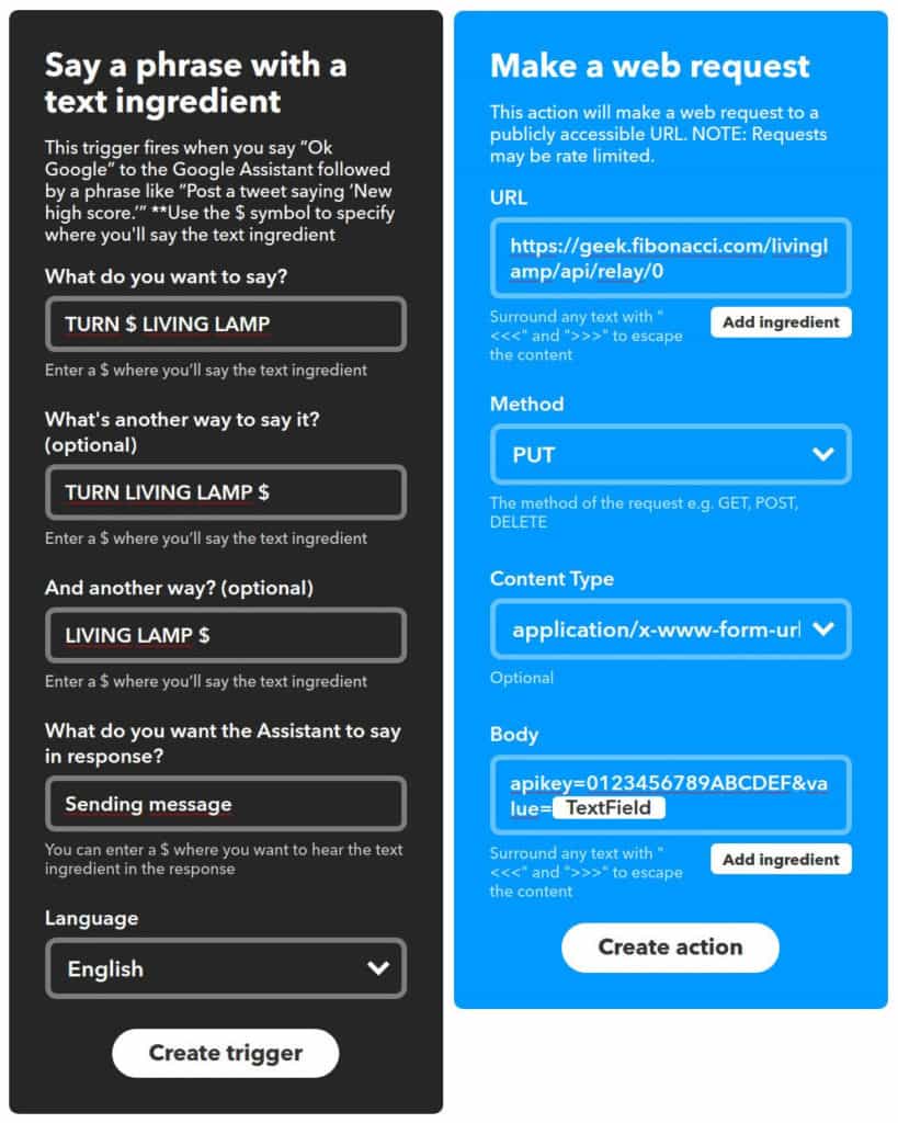
Now let’s configure the applet in IFTTT. You will have to create an account if you have not created one before. Then go to “My Applets” and click on “New Applet”. An applet is a combination of a trigger and an action. Both are provided by “services”. Our trigger will be provided by Google Assistant. Click on the “this” word and look for “google assistant” on the search box.

Each provider could provide one or more services, here we need the “Say a phrase with a text ingredient”. We will use the text ingredient to specify wether we want to switch it on, off or toggle the switch. As you can see in the screenshot below you can configure several (up to 4) different ways to say the command and the dollar sign will be replaced by the ingredient.

Once you have it configured click next and choose an action. In this case the only one provided by WebHooks, the “Make a web request”. We will just fill the fields with the same option as in the cURL command before replacing the value field in the body with “{{TextField}}”, to pass the ingredient that Google Assistant has identified.

ga_02i3

Finally it will ask you to name the applet and once activated you are ready to go. In my case I click and hold the home button in my mobile phone to wake Google Assistant and speak “Turn on living lamp” and enjoy.

NOTE: As you might have noticed the “ingredient” will be a word. ESPurna 1.9.3 (still not realeased) supports “ON”, “OFF” and “TOGGLE” to change the status of the relay. If using a previous version or your device only supports numbers you might want to test the “Say a phrase with a number” trigger service instead. In this case you might want to be able to say “Set living room status to 1”, for instance. Less human-friendly but still usable.

All an all this approach is more flexible than that from Amazon, even thou there are more services involved. Using IFTTT alone, without Google Assistant, can provide an easy way to do schedules or actions depending on, for instance, an email or a tweet. That’s something you can also do with Node-RED for instance but IFTTT provides an easier way to do it…

As always, comments welcome!


The post Using Google Assistant to control your ESP8266 devices appeared first on Tinkerman.


Hacking the Sonoff RF Bridge 433

$
0
0

Itead Studio has been releasing interesting gadgets for the Home Automation community based on a low price tag and extreme hackability. You can google “sonoff” (the main brand for Itead Studio home automation devices) to get more than a million hits, including official pages, reviews and lots of hacks. The ubiquitous ESP8266 (or its sibling ESP8285) is the core of all those devices, using WiFi instead of the traditional RF messages, replacing a remote with mobile apps or voice commands. But also, using custom firmwares like ESPurna, technologies and solutions like MQTT, Node-RED or Home Assistant. But one of the latests devices from the chinese firm tries to bridge the gap between those two technologies: the Sonoff RF Bridge 433.

Itead Studio was kind enough to send me an engineer sample before holidays but I have had very few time to work on it. I should have written this post a month ago. Anyway you can buy one from the Itead Studio webshop or in the usual online markets looking for Sonoff RF Bridge [Aliexpress].

Out of the box

If you had read me before you might know that I have critisized the eWeLink app. It’s not that I didn’t like it. I just couldn’t make it work. With every new Sonoff device I gave it a chance and the outcome was always the same. Until now. Last month I tried it with the RF Bridge and the 4CH Pro and it worked like charm. Don’t know what was wrong. Maybe an uncompatibility with some other service or app in my phone. At some point the problem has been addressed and I could finally test it.

screenshot4s


It works, you can discover the device, force pair mode for any of the 4 available buttons and use them. it also work with Alexa and eWeLink custom skill. Nice. But I just don’t want to use it. I will not go (I have never gone) much into the app, the user experience, the use cases,… because this is about hacking it with he aim of really own the device and have the freedom to choose what 3rd party services you will use with it, if any at all.

The device

Outside

The Sonoff RF Bridge 433 is a small black box with a microUSB port for power, a recessed reset button and three LEDs for notifications (power, custom and radio). The button is connected to GPIO0 on the ESP8266 so it doubles as flash mode button. In the original firmware it sets the device into “discoverable” mode, so you can use the eWeLink app to discover it.

20170721_163918s

MicroUSB and reset button.

20170721_163940s

The three LEDs in the front of the device are used in the original firmware to notify radio usage (red), wifi connection (blue) and power (green)

Short section, right. There is really not much more about it. A sticker with a QR linking to the eWeLink user guide.

Inside

Opening the box is quite easy with the help of a couple of plastic opening tools. Inside the box there is a single PCB with all the components.

20170721_164300s

A single PCB holds all the components

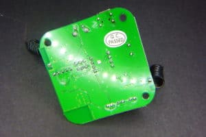
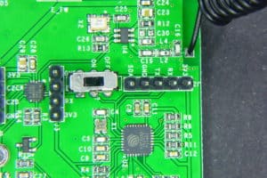
On one of the corners you can spot the PCB WiFi antenna and the ESP8285 (an ESP8266 with a 1Mbyte flash memory embedded) along with the required header to flash it (3V3, RX, TX and GND). You also have access to GPIO2 (labelled SDA) on the same header.

20170810_130816s

In the center of the board you can see the EFM8BB1. An 8-bit microcontroller by SiLabs that manages the radio communication. This is the same microcontroller IteadStudio has used for the Slampher and the Sonoff RF. Moving the real-time encoding and decoding out of the ESP8285 has benefits since those are very time-picky functionalities that could interfere with the WiFi communications.

20170721_164240s

The EFM8BB1 microcontroller is responsible for encoding and decoding radio messages

But the EFM8BB1 is not alone. There is a SYN470R ASK superhet receiver decoding the messages. You might have also noticed two quarter-wavelength wire antennae, one close to the receiver and the opposite one for transmitting.

20170810_130851s

The SYN470R ASK decoder and the receiving wire antenna

20170721_164317s

You can also spot a buzzer for pairing notifications and the ASM1117 regulator.

Finally, a SPDT switch that controlls the communications between the ESP8285 and the EFM8BB1. The communication is done via serial (RX and TX) and that could be a problem when trying to flash a new firmware. Moving the switch to the OFF position you effectively disconnect the communication between both microcontrollers.

20170810_130943s

The back of the board is empty, all the components are on the front

Enough about the PCB. You can check the schematics for the Sonoff RF Bridge 433 yourself at the IteadStudio wiki.

ESPurna

Flashing it

As we have seen the board has all the connections to allow anyone to flash a custom firmware on the ESP8285 (and on the EFM8BB1, but I will focus on the Espressif chip). All you have to do is:

  • Connect the ESP8286 header to your USB2UART programmer (RX to TX, TX to RX and GND to GND)
  • Place the switch in the OFF position
  • Press and hold the reset button
  • And power the device either via the microUSB port or via the 3V3 pin on the same programming header

20170810_130927s

At that moment the ESP8285 will boot into flash mode, ready to get a new firmware. If you are using PlatformIO (recommended), just checkouot the ESPurna repository, browse or open the Atom IDE on the code folder and build and flash the itead-sonoff-rfbridge environment. From the console it would be something like:

pio run -e itead-sonoff-rfbridge -t upload

Done. If you are using Arduino IDE instead check out the instructions from the Arduino IDE page in the ESPurna wiki to configure the environment and flash the board.

Since 1.9.0 ESPurna fully supports Sonoff RF Bridge 433 but the approach the firmware uses is quite different from that on the official app.ç

The ESPurna firmware is released as free open software and can be checked out at my Espurna repository on Bitbucket.

Public API

It turns out that the API between the ESP8285 and the EFM8BB1 is public under the serious name of RF Universal Transceive Module Serial Protocol. The document is spare, has one or two typos and misses some basic information, but it’s good enough to interface the EDM8BB1 from you own ESP8285 firmware.

The key points in the API is that:

  • You can set the device in “listen mode” which basically beeps the buzzer to provide some user interaction
  • Any code the SYN470R decodes the EFM8BB1 will report it to the ESP8285
  • The ESP8285 can send raw codes to the EFM8BB1 and it will forward them

So we have a good enough API to work with. The ESP8285 handles the user interaction, stores codes (there is room for more than a 100 different codes in the emulated EEPROM) and commands the 8-bit microcontroller.

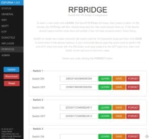
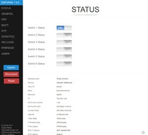
From the ESPurna web UI you can manage the stored codes. By default you have 6 ON/OFF pairs but you can change that in the configuration files, anyway it way more than the 4 codes the official app can handle. Once “learnt”, you can use them from the main status page, like you would with any other switch.

screenshot1s

screenshot2s


Once you have the codes assigned to a certain “virtual” switch you can manage the from MQTT easily by switching the false “relay” on and off:

mosquitto_pub -t /test/rfbridge/relay/0/set -m 1

or using the REST API so you can do that from outside your home too. Check my post about secure access to your IoT devices from the intenet, also with Google Home.

MQTT power

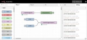
But the firmware also exposes direct access to the Receive Key and Transmit Key Value entry points. That means you can sniff RF messages from Node-RED, for instance, and send them by simply copy paste the codes. Here you have a screenshot of a fully functional interface for the Sonoff RF Bridge 433 in Node-RED. That’s all it takes.

screenshot3s

You can sniff and store as many codes as you want or use other apps or services to send them via MQTT. The Sonoff RF Bridge 433 as a true, transparent, MQTT-433MHz-MQTT bridge.

Will it work with any RF device?

I have a couple of old RF switches sets at home. I have used them in the past and time has come to give them a second life. These have slightly different implementations based on the Manchester encoding but since the code does not matter about the message structure itself it shouldn’t matter, right?

Well, as it turns out one of the remotes (branded Noru) works flawlessly but with the other one (Avidsen) the RF Bridge struggles to understand the messages and often requires several tries before they got learnt. So what’s the difference?

My only guess at the moment is the timing. The code structure is simple:

  • Sync time (2 bytes)
  • Low level time (2 bytes)
  • High level time (2 bytes)
  • Data (3 bytes)

So this is what a Noru message looks like: “24E0 0140 0384 D00358”. That means: 9440us sync time, 320us low time and 900us high time. Data is “D00358”, this identifies the button in the remote. The timing is not necessarily strict, but you can see the high time is 3 times longer than the low time and the sync time is 10 times longer than the high time. And the minimum pulse length is around 320us and that’s about 3KHz. The SYN470R datasheet talks about a max frequency of 5KHz when in sweeping mode. The pulses in the Avidsen look like being faster than that… but more investigation is needed here.

RF relays

But apart from the Avidesen remotes all the other devices I have tested have been a success. All the RF enabled products by IteadStudio, of course but I have also bought some extremely cheap RF relays to play with.

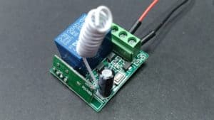
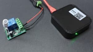
The ones I bought are 1 channel 433MHz enabled relays [Aliexpress]. You can buy them alone, with a remote, with an enclosure and they come also in multiple channels [Aliexpress]. They work best in interlock mode, with two different commands to switch them on and off. This way ESPurna will transmit each code several times to ensure the relay has been switched, otherwise it will only transmit it once.

20170830_174255s 20170830_174320s 20170830_174310s

Anyway it’s a really cheap solution for home automation and start controlling your assets with MQTT, Alexa, Google Home or a bunch of other solutions.

Overall this is an enabling device. If you are still using 433MHz devices at home, or if you decided to stop using them because, you know, you never find the remote when you need it, now it may be time to make them talk MQTT (somewhat).

The post Hacking the Sonoff RF Bridge 433 appeared first on Tinkerman.

Connected power meter

$
0
0

A few weeks ago a user came with a request to add support in ESPurna to a power meter that had been hacked by Karl Hagström. It is a very cheap chinese power meter with plenty of room on the inside, enough to house an ESP8266 module and a DC/DC power supply and the main IC protocol had been reverse engeneered. There even was a repository by the Harringay Maker Space with sample code for an arduino compatible platform.

I found it really interesting so I jumped in and ordered two of them (for 25,20 euros in total). Unfortunately the seller I bought it from has ran out of them. But you can still find them on the usual market places, like these ones [Ebay] or (also with non-EU variants) these ones [Aliexpress].

When I received them I quicky unscrewed the enclosure of one of them and… wow, it looked slightly different than that on Karl’s post but also different from the one the people at Harringay Maker Space had worked with.

p1240281s p1240279s

I went back and forth and I noticed the hack was almost 2 years old and the board was clearly different: different version (unlabelled on Karl’s pictures, version 2014-04-28 on Harringay’s power meter and 2016-12-18 on mine), different board layout with a different connector between the power meter board and the display (7 wires on theirs, 6 on mine). But the most important difference was the main power meter IC. Karl had reverse engineered the ECH1560 on his power meter, a 24pin SOP package (on the back on his device, on the front in Herringay’s power meter). Mine was only 16pin…

p1240274sI had to decipher the IC mark using parts from both devices since the manufacturer had crossed out the marks (they don’t want us to hack it or what?). Finally my best guess was V9261F. I quicky googled it and… bingo!

You will (almost) never be the first one

The Domoticz community is quite active. And they were aready working on supporting this device. Actually the datasheet for the Vango V9261F [datasheet, PDF] is public (contrary to that on the ECH1560). So I just had to “borrow” the work from two of the domoticz community members (kudos to Kapee and Rolo)  and continue from there.

The hack, like with Karl’s method, is based on sniffing the traffic between the power board (where the V9261F sits) and the display board. On this new version there are 6 cables labelled (RX, TX, FREQ, VDD and GND, the sixth is unlabelled). So it strongly looked like being a serial interface. All they had to do was to wire the TX pin to a GPIO in the ESP8266 module and use a software serial library to receive the messages.

The messages looked something like this:

FE 11 01 04 00 00 01 1D 
FE 11 04 6B E5 FF FF 74 BF FF FF 70 5C E2 3A 00 30 02 00 86

There are two messages there, both are responses to a read operation. The first one returns 1 register (each register in the V9261F has 4 bytes) and thus has 3 bytes for the header, 4 bytes for the register and 1 more byte for the checksum, totalling 8 bytes. The other response contains 4 registers and has (3+4*4+1) 20 bytes. The key here was knowing what registers where those. Unfortunatelly the response does not specifiy the register address, only the contents. But as easy as sniffing the TX line, one can sniff the RX line. This is what the microcontroller in the display board requests to the V96261F:

FE 11 80 01 00 00 00 A2
FE 11 19 04 00 00 00 06

Great, so it first requests the SysCtrl register (0x0180, not very useful for us) and then 4 registers starting with 0x0119. What registers are those? Let’s check the datasheet:

  • 0x0119: Average total active power
  • 0x011A: Average total reactive power
  • 0x011B: Average total voltage RMS
  • 0x011C: Average total current RMS

So good 🙂

Wire it

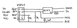
Rolo, at the Domoticz forum has shared a schematic to isolate the TX pin from the ESP8266 module using a PC817 optocoupler [Ebay]. I thought it was a good oportunity to use those “old” ESP01 modules I never use so I prepared a stripboard using his schematic as starting point.

schema

The ESP01 module is supposed to be connected with the antenna to the right, over the PC817 optocoupler

The schematic assumes you power it with a 3V3 source. In the first term I used a 5V source so I had to add a AMS1117-3V3 to the power input. Anything capable of supplying 400mA peak should be enough.

p1240283s

p1240284s

The power source and the ESP01 module and “carrier” board. The blue cable is soldered to the TX pin in the power meter board.

p1240285s

For the second powermeter I used a wemos board, which simplifies the connections. Basically you just need the optocoupler and the input resistor.

p1240286s

p1240290s

p1240288s

You might have noticed I also used two different power sources. Again, you will need 400mA output to be safe. HLK-PM01 [Aliexpress] modules are great for that, but cheaper “open” AC/DC 5V 700mA power supply modules [Aliexpress] will also work.

It is very important that you double check the connections and the weldings. Also, once you have tested it and you want to close the box, hot glue everything so they stay in place. Trust me. You don’t want a wire going loose there.

Support in ESPurna

The ESPurna firmware is released as free open software and can be checked out at my Espurna repository on Bitbucket.

Final step was to integrate the code in ESPurna, so it will benefit from other “goodies” in the firmware (MQTT, REST API, Home Assistant and Domoticz support, WebUI, WiFi configuration, etc). The firmware reports “real time” values (every 6 seconds) to the web client and aggregated (and filtered) values via MQTT to other services.

espurna-v9261f-status

But one bonus that comes with ESPurna is the calibration feature. Because there are some calculations involved in getting the power value from the number the V9261F provides. Same for current or voltage. And there are some “magic numbers” on those calculations. I have not been able to find out what those numbers should be. In section 5.13 of the datasheet talks about calibration registers and formulae but I can’t figure the numbers out…

So instead you can use the power section in the Web UI to calibrate the values you are getting. You are not supposed to write there those “magic numbers”. Instead, you have to write the values the power meter is displaying on the screen and the firmware will do the maths for you.

espurna-v9261f-power

The power calibration tab allows you to introduce the “expected” values for power, current and voltage.

But, what about the ECH1560?

Yeah! That was the first idea. I decided to add support for the ECH1560 in ESPurna too. But this is completely untested and it will almost certainly have bugs. So if you want to give it a try, be ready to debug.

You will have to wire two cables now, instead of one. One for the CLK pin and the other for the MISO line. Use optocouplers too, you’ll stay safer. There is already a device in ESPurna for the ECH1560 (called GENERIC_ECH1560) that assumes the CLK pin is on GPIO4 and MISO on GPIO5. If your setup is different you might want to change the definitions in the hardware.h file:

// -----------------------------------------------------------------------------
// ECH1560
// -----------------------------------------------------------------------------

#elif defined(GENERIC_ECH1560)

    // Info
    #define MANUFACTURER        "GENERIC"
    #define DEVICE              "ECH1560"

    // ECH1560
    #define POWER_PROVIDER      POWER_PROVIDER_ECH1560
    #define ECH1560_CLK_PIN     4
    #define ECH1560_MISO_PIN    5
    #define ECH1560_INVERTED    0

Also, some people has reported their power values are inverted. If you are getting weird power values try changing the ECH1560_INVERTED setting to 1.

Good luck and report back!

The post Connected power meter appeared first on Tinkerman.

Sonoff B1, lights and shades

$
0
0

Six months ago I was reviewing the AiThinker AiLight, a great looking light bulb with an embedded ESP8266EX microcontroller, driven by a MY9291 LED driver. Just before summer IteadStudio released it’s Sonoff B1 [Itead.cc] light bulb, heavily inspired (probably same manufacturer) by the AiLight, at least on the design.

Now that IteadStudio has become popular between the home automation community you can also find the Sonoff B1 on global marketplaces like Ebay or Aliexpress for around 13€.

A closer look at the B1 uncovers some important differences. But before going deeper into the details let me first say that this post will probably look more like a review, at least more than I use to write. And second, yes: ESPurna supports the Sonoff B1 🙂

An unboxing?

Not quite so. I leave that to other people with better skills on the video editing world. Let me just tell you than the “box” is somewhat different from what I expected. You might recall the AiLight box: a simple beige drawer-like box with a “WiFi Light” text and a simple icon. No colors, pictures, specifications,… nothing.

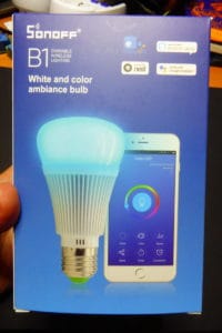
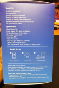
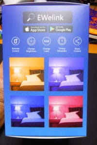
Instead, the Sonoff B1 I received from IteadStudio comes in a colorful box, with the usual pictures and data you can find in retail products.

20170825_161452s20170825_161500s20170825_161513s

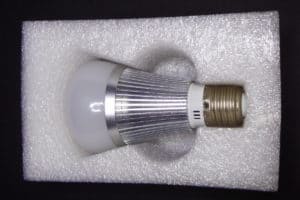
Inside the box the light bulb is comfy housed in a polyethylene foam, along with a quality control certification and a small “getting started” manual in English and Chinese.

20170926_175550s

A heat sink?

Don’t think so. The first thing I noticed when I opened the box was that the bulb was very similar to the AiLight, the second the only visual difference. It certainly looks like a big heat sink. I almost fear touching it while connected. But how much heat can you generate if the light is rated 6W? The bulb body houses a basic AC/DC power supply (90-250VAC to 12VDC) and is accessible unscrewing the metal frame (the heat-sink part from the smooth part with the “sonoff” logo).

20170825_161409s

The AiLight is also 6W and you can safely touch it, even when it has been at full power for a lot of time. The Sonoff B1 shouldn’t be different. So I’m lean towards thinking it’s an aesthetic decision. Unless there are some beefy power LEDs inside.

Power LEDs?

Not all of them. Anyway I think this is the aspect where the B1 clearly differentiates from the AiLight. The later has 8 cold white power LEDs, as well as 6 red, 4 green and 4 blue power LEDs. The Sonoff B1 also has 8 cold white ones. But then it features 8 warm white power LEDs and 3 5050 RGB LEDs!

20170927_180232s

I don’t have a luximeter but the difference when fully white between the two is hard to spot. But the warm white color really makes the difference in favor of the Sonoff bulb. On the other hand, the 3 5050 SMD LEDs are clearly not enough. Even more: since the RGB LEDs are closer to the center of the round PCB, just around the WiFi antenna, the shadow of the antenna is very noticeable if you are using a colored light.

20170926_194524s

Hard to tell which one is brighter for the naked eye…

20170926_194614s

The pic does not justice the difference. The right on is the AiLight with the white power LEDs at full duty. The left on is the Sonoff B1 using the warm white power LEDs (you can see the yellowish color in the wall). The cold white LEDs are brighter but, depending on the room, the warm white LEDs could be more suitable.

20170926_194707s

Both bulbs again, now with the red channel at full duty. No need for words.

20170826_205146s

3 5050 RGB LEDs, 3 shadows of the antenna

20170927_183032s

A view without the cap, red LEDs are at 100% duty cycle, white LEDs are only at 10%…

I think the Sonoff B1 could be a better choice when used to illuminate with a warm white light your living room or your bedroom than the AiLight. If you need a colorful illumination, discotheque moods or a nice cold white for your kitchen, use the AiLight. Another possible (and interesting) use for Sonoff B1 would be as a notification light using traffic light color code, for instance. Clearly visible but not disturbing colors.

The controller?

Not the same. It is actually an ESP8285. In practice, you can talk to it like if it was an ESP2866 with a 1Mb embedded flash using DOUT flash mode. So that’s my recommended configuration.

20170825_161152s

The ESP8285 and required components with the 5050 RGB LEDs

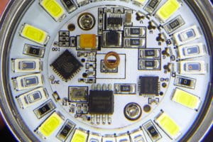
As you can see in the pictures, the PCB is actually 2 PCB, one for the power LEDs and the other one for the microcontroller, some components and the 5050 on the front, a buck converter (12VDC to 3.3VDC for the ESP8285) and the LED driver on the back. The two PCBs are soldered together and glued to the underneath support.

In the AiLight the LED driver is a MY9291 [datasheet, PDF] by My-Semi. The Sonoff B1 uses another My-Semi driver, the MY9231 [datasheet, PDF]. The MY9291 is a 4 channels LED driver but the MY9231 is just 3 channels… so how is it possible to do RGB plus white and warm? Well actually these ICs are daisy chainable, so there are two MY9231 controllers in the Sonoff B1, the first one controlling the white power LEDs and the second the 5050 RGB LEDs.

20170927_180341s

I did not want to remove the glue under the PCB. But you can glimpse one My-Semi controller through the bottom hole.

ESPurna?

The ESPurna firmware is released as free open software and can be checked out at my Espurna repository on Bitbucket.

Sure! You can flash the Sonoff B1 following the same procedure of the AiLight. There are 6 pads on the PCB labelled 3V3, RX, TX, GND, GPIO0 and SDA. You will need to wire the first 5 (tin you cable, apply a small drop on the pad and then heat them together). Connect RX to TX, TX to RX, GND to GND, GPIO0 to GND and finally 3V3 to the 3V3 power source of your programmer. It will then enter into flash mode (GPIO0 is grounded). You can either flash the bin file from the ESPurna downloads section or build your own image (check the ESPurna wiki for docs).

20170826_191932s

Wired flashing of the Sonoff B1

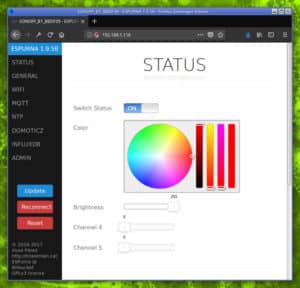
Since ESPurna version 1.9.0 you define and control any number of dimming channels, you can also define the first three to be RGB channels. If you do, the web UI will show you a colorpicker to select the color.

espurna-lightYou can also control it via MQTT. It supports CSS notation, comma separated or color temperature, as well as brightness and status, of course.

// 100% red
mosquitto_pub -t /home/study/light/color/set -m "#FF0000";

// 100% warm white
mosquitto_pub -t /home/study/light/color/set -m "0,0,0,0,255";

// 300 mired color temperature
mosquitto_pub -t /home/study/light/color/set -m "M300";

// 4000 kelvin color temperature
mosquitto_pub -t /home/study/light/color/set -m "K4000";

Of course you can also use Home Assistant MQTT Light component. The configuration would look like this:

light:
  - platform: mqtt
    name: 'AI Light TEST'
    state_topic: '/home/study/light/relay/0'
    command_topic: '/home/study/light/relay/0/set'
    payload_on: 1
    payload_off: 0
    rgb_state_topic: '/home/study/light/color'
    rgb_command_topic: '/home/study/light/color/set'
    rgb: true
    optimistic: false
    color_temp: true
    color_temp_command_topic: '/home/study/light/mired/set'
    brightness: true
    brightness_command_topic: '/home/study/light/brightness/set'
    brightness_state_topic: '/home/study/light/brightness'
    white_value: true
    white_value_command_topic: '/home/study/light/channel/3/set'
    white_value_state_topic: '/home/study/light/channel/3'

Either way, flashing a custom firmware like ESPurna on a 13€ Sonoff B1 [Ebay] device allows you to first fully control your device (no connections outside your home network if you don’t want to) and second, make it interoperate with other services like Home Assistant, Domoticz, Node-RED or any other MQTT o REST capable services.

After all, I’m talking about Technological Sovereignty.

The post Sonoff B1, lights and shades appeared first on Tinkerman.

Yet another WiFi light bulb

$
0
0

Eight months ago I reviewed and hacked the AiLight WiFi light bulb by AiThinker. By the time there was a number of people doing the same because of a key reason: it sports an ESP8266 microcontroller and it is based on the OpenLight by Noduino, that had already provided open source code for the LED driver inside, the MY9291.

Let time pass and I was doing the same with the Sonoff B1 light bulb by Itead Studio. That was two months ago and the conclusion was that the AiLight is brighter the the B1 but the lacks warm white channel the Sonoff bulb has.

And now here I have yet another WiFi light bulb, the Arilux E27 Smart Bulb. It looks pretty much like the other two, same shape, same microcontroller, same driver, but different base again and most important: different LEDs. So how does this one compare to the other ones?

Arilux E27 Smart Bulb

Arilux has a big catalog of lights, from security outdoor lights to fancy Christmas lights or disco lights. The Arilux E27 (its proper name is “Smart Bulb”) it’s a 7W RGBW light bulb with WiFi (IEEE 802.11b/g/n) that can be used on any E27 socket around the globe (85 to 285VAC supported).

20171109_142859s

20171109_142757s

It has an ESP8266 with a 1Mb flash memory like it’s siblings and the same light driver as the AiThinker light, the 4-channel MY9291. The Sonoff B1, on the other hand, uses two daisy-chained MY9231, three channels each and uses 5 of the 6 channels available.

20171109_142639s

Flashing it

Of course, you might want to use a custom firmware with your new light bulb, something that supports MQTT, Home Assistant, REST API, with a nice web interface. Something like ESPurna, for instance 🙂

Anyway, you might need to wire the bulb to flash it the first time, from then on OTA is a better option. Like the other two light bulbs, this one has a properly labeled pads on the main circuit board where you can solder thin cables and use your USB2UART programmer.

20171108_125303s

20171108_125324s

Wiring it is simpler than it may seem. Heat the pad, leave a drop of tin on it, tin your wire also and then heat them together. You will only need a fraction of a second to have the cable connected to the pad. Then just connect it to your programmer. Remember it’s a 3V3 device and you have to connect IO0 to ground before powering the board so it enters into flash mode. The follow the instructions of your firmware of choice (here the ones for ESPurna with AiLight) and you are good to go.

AiLight vs. Sonoff B1 vs. Arilux E27

20171109_143846s

LEDs

These three bulbs are functionally identical but have obvious differences due to the type of LEDs they use (aside from the warm white channel in the Sonoff B1). The table below tries to summarize the differences between the three:

Channel Sonoff B1 Arilux E27 AiThinker AiLight
Red 3x 5050 RGB 6 6
Green (see above) 4 4
Blue (see above) 4 4
Cold White 8 8 8
Warm White 8 - -

But of course the number of LEDs is not enough to compare them. Actually you can see in the pictures that the power LEDs in the bulbs are quite different one from the other (5050 RGB LEDs aside).

20170927_180232s

Sonoff B1 LEDs, notice the 3 5050 RGB LEDs in the center board, too close to the antenna

20171108_124912s

The Arilux light bulbs, very similar to the AiLight but different kind of power LEDs

20170224_210528x

The power LEDs in the AiLight are bigger, brighter and evenly located, an overall better result

Light power

So, how do they compare when talking about brightness? In my previous post about the Sonoff B1, I noticed the 5050 RGB LEDs were clearly not enough, much much less bright than the power LEDs in the AiLight. It was very obvious (you can check the pictures on that post), but subjective appreciation after all.

This time I have decided to do a more “scientific” experiment. As it happens I have several luximeters at home for another project, so why not use one of those to compare the three bulbs in a controlled environment. The luximeter I have used is a UNI-T UT383. You can buy one for around 12€ from Aliexpress (UNI-T UT383 at Aliexpress) or Ebay (UNI-T UT383 at Ebay). It is on the cheap side and there is no information about how it performs for different wavelengths (only they have been calibrated at 2856K), but it should be enough to compare the three bulbs brightness.

20171110_162814s

UNI-T UT3838 luximeter

So here is the experiment set up: the three light bulbs have been tested using the luximeter at a distance of 50cm, without obstacles that might reflect light (>90 3D degrees clean around the light). I have recorded the value in luxes for each channel at 100% duty cycle (other channels off). I have also tested the three color channels together (red + green + blue) and all the channels together. This chart shows the results:

Channel Sonoff B1 Arilux E27 AiThinker AiLight
Red 0 3 51
Green 5 27 72
Blue 9 55 149
Red + Green + Blue 17 92 287
Cold White 227 192 282
Warm White 220
All 461 282 548

The AiLight power LEDs really make the difference. The Arilux colour LEDs perform better than the poor 3 5050 RGB LEDs in the Sonoff B1, but the later has the advantage of having a second set of white LEDs (warm white in this case) so when everything is at full power it’s actually brighter than the Arilux, but still far from the AiLight.

Price

So it looks like the AiLight might be the best option for most use cases, except when you need a warm white light bulb. The final argument might be the price.

Product Aliexpress Ebay
Sonoff B1 14.09€ [Sonoff B1 @ Aliexpress] 11.90€ [Sonoff B1 @ Ebay]
Arilux E27 11.24€ [Arilux E27 @ Aliexpress] 16.22€ [Arilux E27 @ Ebay]
AiThinker AiLight 12.58€ [AiLight @ Ebay]

So you can buy any of the three light bulbs for around 12€ so there is no big difference here.

Conclusions

The final verdict is very much the same as when I reviewed the Sonoff B1. If you need light power go for the AiLight. The Sonoff B1 can be a good option if you are looking for a warm white light since it’s the only one that offers such possibility. Both the Sonoff and the Arilux lights can be a good option too when looking for a notification light, a traffic light kind of visual notification for instance. The Arilux colors are a bit brighter than the ones in the Sonoff B1 (those 5050 LEDs are not a good idea), but still way fainter than the ones in the AiLight. So for most cases, you will probably want to go for the AiLight unless you happen to find a good deal on any of the three…

The post Yet another WiFi light bulb appeared first on Tinkerman.

Sonoff S31, a world apart

$
0
0

It’s not that other Sonoff products are not “serious” business, but there are a number of design changes in the Sonoff S31 that make this new product a world apart. For the functional point of view it looks like a S20 with POW-powers, but they have redesigned the product completely. The result is very very interesting.

  • Revamped case, more compact and sturdy
  • Redesigned PCB, actually 2 different PCBs for main and control
  • Different power monitor chip: the CSE7766 (same as in the new POW R2) replaces the HLW8012

The only drawback: it’s only compatible with plug types A & B, tat is central and north-america and few other countries. I’d love to see a S31-EU schuko version!

You can buy the S31 from Itead (see link above) or via the usual marketplaces. Actually the S31 is slightly cheaper [Ebay] on some of them.

Not an unboxing

You know I don’t do unboxings so  this is not an unboxing. They just happen to be pictures with the device in a box.

p1240882s

p1240883s

p1240884s

The device itself is kind of pretty, compact and robust. It has some appealing design choices (outside and inside) and the way everything fits together (see more pictures below) is great.

Aside from the male and female type A plugs, you have a ON/OFF button on the dark gray side and two LEDs. The red LED closer to the side shows the relay status and the blue one, closer to the plug is used for notifications.

p1240886s

p1240887s

p1240890s

Every time I look at a USA plug I get the same feeling. Ooooh, how is that you are so sad? But this time it was also my face. The slick design of the device gets completely ruined with the two adapters (C to A and A to C).

p1240891s

S20 Smart SocketThe design is very different from the S20. The later is used by several manufacturers for their branded smart plugs, so it’s probably someone else’s design. I can’t tell about the S31 but the level of integration makes me think it’s an adhoc design.

Opening it

Opening the case to hack the device it’s not hard. The only tricky step is to measure the strength you have to apply to first remove the dark grey cap where the ON/OFF button is.

p1240894s

p1240896sThen you have to slide the corners to reveal 3 small Philips screws that will let you remove the top completely. The bottom side (the one with the male plugs) seems to be glued to the PCB so it is not easy to remove without risking breaking something. Anyway you don’t need to access the bottom side of the PCB where there are only a few passives and a SO8 chip, probably the switching power supply chip.

p1240897s

p1240898s

Compact design

The design is based on two PCBs. The bigger one for the AC connections, AC/DC transformer and relay. And the smaller one for the the DC circuitry, including the ESP8266, an SPI flash memory and the CSE7766 power monitoring chip. It sounds like a good idea but it gets somewhat screw because they don’t actually isolate AC from DC. AC is in the secondary PCB too since the power monitor chips needs access to mains. Also the distance between AC and DC traces is thinner than what would be desirable.

p1240877s

p1240878s

Notice that, unlike the S20 where the PCB is connected to the plug barrels via wires, in the S31 the connectors are soldered to the PCB. This saves some space for sure but probably makes the device more sturdy too. The removable cap has separators to ensure the contacts are isolated from other components, including the small cables from the transformer.

p1240879s

For a complete photo book of the S31 you can check the FCC database photos.

The CSE7766 power monitoring chip

IteadStudio has switched from the HLW8012 chip to the CSE7766 for power monitoring with their latests products, the S31 and the POW R2. The reason might be that the new chip by Chinese manufacturer Chipsea offers a more stable reading, according to the first tests. The good news are that both chips are pin compatible even thou the protocol is very different.

You might remember from my post about the HLW8012 that this IC uses two pins to output power and current/voltage as variable-frequency square wave. Those pins are number 6 and 7 in the SO8 package. Pin 8 is used in the HLW8012 as an input pin to select whether the output in pin 7 would be proportional to the current or the voltage.

The CSE7766 [datasheet, PDF] uses a serial protocol instead. At the moment only TX line (pin 6) is enabled. The RX line in pin 8 is flagged as “reserved” in the datasheet. Pin 7 outputs a 50% duty cycle pulse with frequency proportional to the active power, just like the HLW8012.

hlw8012-circuit

HLW8012 suggested application

cse7766_application

CSE7766 suggested application with isolation

So you see that on both chips have the same AC interface (left side of the chip) and a similar interface on the MCU part (right side). Actually pins 6 and 7 are outputs and pin 8 is an input on both chips.

Mind that the CSE7766, just like the HLW8012, ties the logic ground to the mains neutral line. This is commonly known as “hot ground”. It’s not bad by itself as long as ground is not exposed outside the case.

But

We all know about Itead products. They have walked a long path since the first Sonoff Basic (or Sonoff WiFi). But still, they do not provide any electrical safety certifications (ETS, UL, ETSI) with their products. They have applied for FCC, claim to be CE and comply with RoHS but EE and professional electricians will probably not install these devices. It’s true the S31 is a plug-and-play device, no electrician required, but in some sense it’s an “AS IS” product. You are a maker, right?

Even thou IteadStudio is improving with every design, safety distance between AC and DC traces is not met.

The POW and S31 have the caveat of being non-isolated devices. Mains are connected to the logic ground and the power monitor IC output is not isolated from the MCU. Even thou the datasheet suggests an isolated application using an optocoupler I have not seen it in the S31. So please, take all the safety precautions when the PCB is exposed.

Flashing ESPurna on the S31

REMEMBER: do not do this while the device is connected to mains. The logic ground in the device is connected to the mains neutral line.

Flashing the S31 with custom firmware requires soldering some wires or a header to the pads at the edge of the small PCB. These pads expose (not only) GND, 3V3, RX and TX. Just connect them to your USB2UART programmer. Then press and hold the button (which is tied to GPIO0) and connect the programmer to your computer so it will power the board.

With GPIO0 connected to GND (that’s what the button does) the ESP8266 will enter flash mode. You will then be able to flash ESPurna (or any other firmware) to the device via serial from your favorite IDE or from the console using esptool.

p1240877seESPurna supports the Sonoff S31 since version 1.12.6. It can control the relay, the notifications LED and report current, voltage, active power and energy to Thingspeak, InfluxDB, Home Assistant, Domoticz or any other service via MQTT.

espurna-s31That’s it. You might have notice I’m not writing as much as I used to a few months ago. I happen to be quite busy lately which is not bad news. But I really miss to be able to spend some more time exploring new devices…

See you soon, hopefully!

The post Sonoff S31, a world apart appeared first on Tinkerman.

Useful notifications from your home appliances using Node-RED

$
0
0

Some time ago I worked on a home project to get a notification when my washing machine had done its job based on monitoring its power consumption. There was a good reason for that, the machine was outside the house and I had already forgotten about the laundry several times. And when that happens your only option is to wash it again, because it really smells musty…

Monitoring your appliances

Use ESPurna 🙂

OK, there are different ways to get the info about power consumption. But since we want to be able to process the data ourselves most commercial products won’t be suitable unless we modify it.

Alternatively, those that use radio communication to send data from the meter to the base station might be suitable for a man-in-the-middle hack. For instance, if you own an Efergy power meter you must know you can sniff the data it sends using a simple RTL-SDR dongle.

But for most cases, your best chance is to get your hands on a commercial product with an ESP8266 chip in it and change the firmware to suit your needs. You can write your own or use an existing firmware like ESPurna, that already supports a bunch of power metering smart switches.

What info do you need?

The idea is to report (via MQTT) power data from each individual appliance very minute. You can then use Node-RED along with InfluxDB and Grafana (or Graphite) to receive, persist and graph your data like in the image below.

grafana-consum

There is a lot of useful information you can get just by graphing this data: device power footprint, device health, power consumption habits, duty cycles (for the fridge, for instance), max minute power (a key factor in your electricity bill) and, of course, foresee your next bill.

The info you will be getting has two main limitations: sensor precision (and error) and data granularity. Your sensors (clamps, power monitoring chips,…) will have a precision of maybe 5, 10 or 20W. And, even thou you are maybe reading them every few seconds you are probably averaging to get minute readings.

With this info, you will not be able to “see” an LED light turning on and off and you will probably get a baseline of a few tens of watts that you won’t know where they exactly come from. But for some “big” appliances like your washer machine, your dryer, the oven, the dishwasher and such, you will get a pretty accurate footprint since their duty cycles usually last for 30 minutes, 60 minutes or even more.

One thing you can do is to monitor their power consumption to know when they are done (my washer machine example before). But since you have some significant data you can think on adding a bit more info to that “your laundry is done” message.

Analysing the data with Node-RED

The simplest analysis you can do on the power data is to know if the appliance is using any power at all. A value over 0W would then trigger a counter that will be aggregating energy (power times time) until the power goes back to 0W.

Problem is that some appliances might have duty cycles with periods of inactivity and you might also face the problem of having spurious or non-zero baseline power values (those damned LED pilots!). So you might want to set the power threshold to something different than 0 and maybe also set a “grace time” before triggering the done event.

I’ve been doing this already using a function node in Node-RED for some time now. But now that I wanted to add more info and connect more appliances to the flow I decided to put all the logic into a proper Node-RED node.

node-red-contrib-power-monitor

The node-red-contrib-power-monitor node is released under the Apache 2.0 license and can be installed from the Node-RED Manage Palette, using npm or checked out from my node-red-contrib-power-monitor repository on GitHub.

The node (node-red-contrib-power-monitor) accepts a real number as an input payload (in Watts) and does the analysis of the info based on 3 settings: the power threshold, a start grace period and a stop grace period.

The node installation is very simple and it does not have any external dependency. You can install it directly from the Manage Palete in you Node-RED UI or using npm from your node-red folder (typically ~/.node-red):

npm i node-red-contrib-power-monitor

Using it

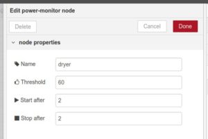
The node configuration allows you to make it match the appliance power footprint with simple settings:

  • Name: Name of the appliance. Will be attached to the output object.
  • Power threshold: Value (in watts) to tell whether the appliance is running or not, an ideal value would be 0 (0W if not running).
  • Start after: Number of messages with readings over the threshold to trigger a start event.
  • Stop after: Number of messages with readings below the threshold to trigger a stop event.

node-red-mimosa-1

Examples

My washer machine below shows a clear and easy to analyze pattern. The power baseline is noiseless (I use a Sonoff POW R2) and the footprint does not show any 0W valley in between. Setting the default values for the node configuration (0W threshold and 1 for start and stop after counts) would work just fine.

washer

The dryer is more tricky, but still easy. As you can see the base line is not that clear (I’m using a Sonoff POW and it reads noise of up to 5W). But the activity power value is very obvious and over 500W constantly. Once it’s done it enters a maintenance cycle to prevent wrinkles that lasts for an hour but the drying cycle is already finished. I’m using a threshold of 100W and leave the start and stop after counts to 1.

dryer

Finally, the dishwasher shows a more complex pattern with 3 different heating periods with low power activity in the middle raging from around 8W to more than 50W. In the end, there is a standby period with readings of around 3W. I’m using a custom board based on the HLW8012 power monitoring chip here, the same as in the POW but the baseline is pretty clean and reads 0W. I use a 5W threshold here but combined with a value for the start and stop counts of 5 to prevent false positives.

dishwasher

Output

Each node will provide real-time info about the running time and energy consumption so far for that given cycle.

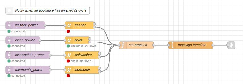
The output is split into two, a connector for the start event and another one for the stop event. The start event is just that, a JSON payload with an event type “start” and the name of the appliance. The stop event adds a couple of very useful values: the total time the appliance has been running in seconds and the total energy in kWh.

node-red-mimosa

You might want to pre-process this info before feeding it to a template node to build a message. In the example above the “pre-process” function node calculates the time in minutes and the cost, assuming a flat rate, but it since you know the current time and the total running time you can make a fair estimate in case you have some kind of time discrimination.

Pre-process code:

msg.payload.time = Math.round(msg.payload.time / 60);
msg.payload.cost = Math.round(msg.payload.energy * 16.66) / 100;
return msg;

Message template (mustache syntax):

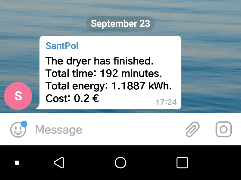
The {{ payload.name }} has finished.
Total time: {{ payload.time }} minutes.
Total energy: {{ payload.energy }} kWh.
Cost: {{ payload.cost }} €

Nice notifications using Telegram

Now that we have all the info it’s time to set up nice notifications. A while ago Germán Martín published a screenshot of his phone receiving a notification from his @iotfridgesaver project. He was also using ESPuna and Node-RED and the results where superb. I just had to copy him 🙂

Creating a Telegram bot and start sending messages from Node-RED is really easy. You can find a lot of resources on the Internet so I won’t go into the details. Just a small script of what you have to do:

  • Open a chat with @BotFather he-she-it will guide you through the process of creating a bot.
  • Install the node-red-contrib-telegrambot node in your Node-RED
  • Configure the token of the node to that provided by the @BotFather
  • You will also need a chatId where the bot has to send the messages. The easiest way is to use a bot like @my_id_bot. If you open a chat with it it will tell you your chatId so your bot will send you direct messages. If you invite @my_id_bot to a group it will tell you the group ID, very useful if you want to share notifications with someone else.

The node-red-contrib-telegrambot accepts a JSON payload with the info to send. You can use this template to build it from the previous payload:

{
    "chatId": 224857347,
    "type": "message",
    "content": "{{ payload }}"
}

You can hardcode the chatId in the node or pass it as a parameter like in the example above. The result will look like this:


screenshot_2018-09-23-17-28-33

Cool?

The post Useful notifications from your home appliances using Node-RED appeared first on Tinkerman.

Automated unit testing in the metal

$
0
0

Unit testing your code is peace of mind. It has two main direct benefits that impact on your confidence about the code you are writing:

  • Testing expected behaviors
  • Avoiding regressions (i.e. breaking something that was working fine before)

Unit testing embedded systems is a bit more involved since there is the additional constraint of the hardware itself, sometimes more than one device or even different platforms. Quitting (or not even thinking about it) is the easy answer to the problem. All of us have debugged expected behaviors with inline prints. But automating some of these tasks have a huge benefit on the code quality and development speed.

Automating builds

I have been doing automated builds for some time now. This is the very first (basic) way to test your code: does it build? For some projects, like ESPurna, it really makes the difference since it has so many different targets and setting combinations it would be a nightmare to test them all manually. Instead, we are using Travis to build several fake images with different combinations to actually test that most of the code builds, i.e. it doesn’t have typos, unmet dependencies,…

Travis also provides a way to create deployment images for the different supported boards in ESPurna. When you download a binary image from the releases page in the ESPurna repository, that file has been automatically created by Travis from a tagged release. That is so cool! You can see how this is done in the .travis.xml file in the root of the repository.

But this is not what I wanted to talk about here.

Existing options

The fact that the project builds, does not mean that it works. The only way to really know that it does what it is supposed to do is to test it on the hardware. This is where we must start using special tools to evaluate conditions (actual versus expected results) and provide an output. This output will probably be via the serial port of the device, although we could think about other fashionable ways to show the result (LEDs, buzzers,…).

Here we have specific tools to do the job. These tools are very much like their “native” counterparts, used for desktop or web languages like Java, PHP, Python… They are usually referred to as testing frameworks. If you are using the Arduino framework you should know about some of these solutions:

  • ArduinoUnit. It has no recent activity but it’s still the preferred choice by many people. There are two relevant contributors: Warren MacEvoy and Matthew Murdoch.
  • AUnit. It is actively developed by Bryan Parks and it has no other relevant contributor.
  • GoogleTest. It is a generic C++ test suite but they have recently started developing support for Arduino framework. It is very active and has a big community but it is still a WIP.
  • ArduinoCI. It started in 2018 just like the AUnit test suite but has had no activity since September and remains as “beta”. Anyway, it claims to have a really interesting set of features. It is based around mocked-up hardware. It has a single main developer named Ian.
  • PlatformIO Unit Testing. This is the only non-free and closed solution. And that’s a pity since it has really impressive options.

There are other available options like Arduino-TestSuite or ArduTest, but they are abandoned.

Visually testing it

All the tools above allow you to “visually” test the code. I mean: you run the tests and they will output a result on the serial monitor. “PASSED” or “OK” mean everything is good. The tools in the previous section allow you (or will allow you) to do that, either on the hardware itself or in a mocked-up version of the hardware.

I will focus here on two of the tools above: AUnit and PlatformIO Unit Test. Both are free to use in this stage and provide a very similar feature set. The project I’ll be using to test them is something I’ve been working recently: an RPN calculator for ESP8266 and ESP32 platforms.

The RPNlib library is released under the Lesser GPL v3 license as free open software and can be checked out at my RPNlib repository on GitHub.

The library is an RPN calculator that can process c-strings of commands and output a stack of results. Testing this is quite simple: you have an input and an output you can compare to the expected output. Let’s see how this can be tested with both solutions.

Testing it with AUnit

AUnit is a testing library by Brian Park. It’s inspired and almost 100% compatible with ArduinoUnit but it uses way less memory than the later and supports platforms as ESP8266 or ESP32. It features a full set of test methods and allows you to use wrapper classes with setup and teardown methods to isolate your tests. That’s pretty cool.

Here you have an example of usage with one of those classes and the output:

#include <Arduino.h>
#include <rpnlib.h>
#include <AUnit.h>

using namespace aunit;

// -----------------------------------------------------------------------------
// Test class
// -----------------------------------------------------------------------------

class CustomTest: public TestOnce {

    protected:

        virtual void setup() override {
            assertTrue(rpn_init(ctxt));
        }

        virtual void teardown() override {
            assertTrue(rpn_clear(ctxt));
        }

        virtual void run_and_compare(const char * command, unsigned char depth, float * expected) {
            assertTrue(rpn_process(ctxt, command));
            assertEqual(RPN_ERROR_OK, rpn_error);
            assertEqual(depth, rpn_stack_size(ctxt));
            float value;
            for (unsigned char i=0; i<depth; i++) {
                assertTrue(rpn_stack_get(ctxt, i, value));
                assertNear(expected[i], value, 0.000001);
            }
        }

        rpn_context ctxt;

};

// -----------------------------------------------------------------------------
// Tests
// -----------------------------------------------------------------------------

testF(CustomTest, test_math) {
    float expected[] = {3};
    run_and_compare("5 2 * 3 + 5 mod", sizeof(expected)/sizeof(float), expected);
}

testF(CustomTest, test_math_advanced) {
    float expected[] = {1};
    run_and_compare("10 2 pow sqrt log10", sizeof(expected)/sizeof(float), expected);
}

testF(CustomTest, test_trig) {
    float expected[] = {1};
    run_and_compare("pi 4 / cos 2 sqrt *", sizeof(expected)/sizeof(float), expected);
}

testF(CustomTest, test_cast) {
    float expected[] = {2, 1, 3.1416, 3.14};
    run_and_compare("pi 2 round pi 4 round 1.1 floor 1.1 ceil", sizeof(expected)/sizeof(float), expected);
}

// -----------------------------------------------------------------------------
// Main
// -----------------------------------------------------------------------------

void setup() {

    Serial.begin(115200);
    delay(2000);

    Printer::setPrinter(&Serial);
    //TestRunner::setVerbosity(Verbosity::kAll);

}

void loop() {
    TestRunner::run();
    delay(1);
}

As you can see, you can define any specific testing methods in the library and create and use them directly from the testF methods. This way you can create new tests very fast. Now I just have to build and upload the test to the target hardware, in this case, an ESP32 board:

$ pio run -s -e esp32 -t upload ; monitor
--- Miniterm on /dev/ttyUSB0  115200,8,N,1 ---
--- Quit: Ctrl+C | Menu: Ctrl+T | Help: Ctrl+T followed by Ctrl+H ---
ets Jun  8 2016 00:22:57

rst:0x10 (RTCWDT_RTC_RESET),boot:0x13 (SPI_FAST_FLASH_BOOT)
configsip: 0, SPIWP:0xee
clk_drv:0x00,q_drv:0x00,d_drv:0x00,cs0_drv:0x00,hd_drv:0x00,wp_drv:0x00
mode:DIO, clock div:2
load:0x3fff0018,len:4
load:0x3fff001c,len:952
load:0x40078000,len:6084
load:0x40080000,len:7944
entry 0x40080310
TestRunner started on 4 test(s).
Test CustomTest_test_cast passed.
Test CustomTest_test_math passed.
Test CustomTest_test_math_advanced passed.
Test CustomTest_test_trig passed.
Test test_memory passed.
TestRunner duration: 0.059 seconds.
TestRunner summary: 4 passed, 0 failed, 0 skipped, 0 timed out, out of 4 test(s).

You can check the full AUnit test suite for the RPNlib in the repo.

Testing it with PlatformIO

Let’s now see how you can do the very same using the PlatformIO Unit Test feature. As you can see it’s very much the same, albeit you don’t have the wrapping class feature by default, but you can still use helper methods. Of course, this means you have to take care of the code isolation yourself.

#include <Arduino.h>
#include "rpnlib.h"
#include <unity.h>

// -----------------------------------------------------------------------------
// Helper methods
// -----------------------------------------------------------------------------

void run_and_compare(const char * command, unsigned char depth, float * expected) {

    float value;
    rpn_context ctxt;

    TEST_ASSERT_TRUE(rpn_init(ctxt));
    TEST_ASSERT_TRUE(rpn_process(ctxt, command));
    TEST_ASSERT_EQUAL_INT8(RPN_ERROR_OK, rpn_error);

    TEST_ASSERT_EQUAL_INT8(depth, rpn_stack_size(ctxt));
    for (unsigned char i=0; i<depth; i++) {
        TEST_ASSERT_TRUE(rpn_stack_get(ctxt, i, value));
        TEST_ASSERT_EQUAL_FLOAT(expected[i], value);
    }

}

// -----------------------------------------------------------------------------
// Tests
// -----------------------------------------------------------------------------

void test_math(void) {
    float expected[] = {3};
    run_and_compare("5 2 * 3 + 5 mod", sizeof(expected)/sizeof(float), expected);
}

void test_math_advanced(void) {
    float expected[] = {1};
    run_and_compare("10 2 pow sqrt log10", sizeof(expected)/sizeof(float), expected);
}

void test_trig(void) {
    float expected[] = {1};
    run_and_compare("pi 4 / cos 2 sqrt *", sizeof(expected)/sizeof(float), expected);
}

void test_cast(void) {
    float expected[] = {2, 1, 3.1416, 3.14};
    run_and_compare("pi 2 round pi 4 round 1.1 floor 1.1 ceil", sizeof(expected)/sizeof(float), expected);
}

// -----------------------------------------------------------------------------
// Main
// -----------------------------------------------------------------------------

void setup() {
    delay(2000);
    UNITY_BEGIN();
    RUN_TEST(test_math);
    RUN_TEST(test_math_advanced);
    RUN_TEST(test_trig);
    RUN_TEST(test_cast);
    UNITY_END();
}

void loop() {
    delay(1);
}

To test it you can use the built-in test command in PlatformIO Core.

$ pio test -e esp32
PIO Plus (https://pioplus.com) v1.5.3
Verbose mode can be enabled via `-v, --verbose` option
Collected 2 items

=== [test/piotest] Building... (1/3) ===
Please wait...

=== [test/piotest] Uploading... (2/3) ===
Please wait...

=== [test/piotest] Testing... (3/3) ===
If you don't see any output for the first 10 secs, please reset board (press reset button)

ets Jun  8 2016 00:22:57
rst:0x1 (POWERON_RESET),boot:0x13 (SPI_FAST_FLASH_BOOT)
configsip: 0, SPIWP:0xee
clk_drv:0x00,q_drv:0x00,d_drv:0x00,cs0_drv:0x00,hd_drv:0x00,wp_drv:0x00
mode:DIO, clock div:2
load:0x3fff0018,len:4
load:0x3fff001c,len:952
load:0x40078000,len:6084
load:0x40080000,len:7944
entry 0x40080310
test/piotest/main.cpp:175:test_math	[PASSED]
test/piotest/main.cpp:176:test_math_advanced	[PASSED]
test/piotest/main.cpp:177:test_trig	[PASSED]
test/piotest/main.cpp:178:test_cast	[PASSED]
-----------------------
4 Tests 0 Failures 0 Ignored

=== [TEST SUMMARY] ===
test/aunit/env:esp8266	[IGNORED]
test/aunit/env:esp32	[IGNORED]
test/piotest/env:esp8266	[IGNORED]
test/piotest/env:esp32	[PASSED]
=== [PASSED] Took 9.84 seconds ===

Automating your tests

Next step would be to run these tests unassisted. That’s it: every time you commit a change to the repo, you want to run the tests on the metal to ensure the results are the expected ones and nothing is broken. Now, this is more involved and both options above (AUnit and PlatformIO) have solutions for that.

The AUnit solution is based on the AUniter script, also maintained by Brian, and Jenkins, an open source continuous integration tool you can install locally or in a server of your own. The AUniter script is actually a wrapper around the Arduino binary in headless mode. This implies two strong conditions for me: a specific folder structure and pre-installed libraries. PlatformIO is more flexible here. Of course, if you are already using the Arduino IDE these conditions might not be hard to meet. Still, you are pretty much limited by the possibilities of the IDE. Maybe when the ArduinoCLI project would leave the alpha stage this will change.

The PlatformIO solution supports a number of CI tools, including Jenkins and Travis. Travis is a very good option since it integrates very well with GitHub or GitLab, so you can have a cloud solution for free. But you might say: “How am I suppose to plug the hardware to the GitHub servers?”. Well, the very cool think about PlatformIO is that it supports remote flashing, deploying and testing. The bad news is that these features are not for free and you will have to have a Professional PIO Plus account which is USD36/year for non-commercial products.

Remote testing with PlatformIO

Let me go briefly through the steps to set a testing server locally so you can use it from Travis with PlatformIO. Basically, you will need to have PlatformIO Core installed and a PlatformIO Agent running connected to your PIO Plus account. Let’s assume you start with a new Raspbian installation on a Raspberry PI (with internet access already configured).

Let’s first install PlatformIO Core (from the Installation page in the documentation of PlatformIO):

$ sudo python -c "$(curl -fsSL https://raw.githubusercontent.com/platformio/platformio/develop/scripts/get-platformio.py)"

And now register to our PIO Plus account (the first time it will install some dependencies):

$ pio account login
PIO Plus (https://pioplus.com) v1.5.3
E-Mail: ************
Password: 
Successfully authorized!

And request a token, you will be using this token to start the agent on boot and also to run the tests from Travis:

$ pio account token
PIO Plus (https://pioplus.com) v1.5.3
Password: 
Personal Authentication Token: 0123456789abcdef0123456789abcdef01234567

Now, try to manually start the agent. You can see it’s named after the Raspberry Pi hostname, acrux in this case:

$ pio remote agent start
2018-12-26 22:57:48 [info] Name: acrux
2018-12-26 22:57:48 [info] Connecting to PIO Remote Cloud
2018-12-26 22:57:49 [info] Successfully connected
2018-12-26 22:57:49 [info] Authenticating
2018-12-26 22:57:49 [info] Successfully authorized

We are almost ready to run code remotely, just some final touch. Add your user to the dialout group so it has access to the serial ports:

$ sudo adduser $USER dialout

And make your life a little easier by using udev rules to create symlinks to the devices you have attached to the Raspberry Pi, this way you will be able to refer to their ports “by name”. You can first list all the connected devices to find the ones you want. In this example below I had just one Nano32 board which uses a FTDI chip:

$ lsusb
Bus 001 Device 005: ID 0403:6015 Future Technology Devices International, Ltd Bridge(I2C/SPI/UART/FIFO)
Bus 001 Device 003: ID 0424:ec00 Standard Microsystems Corp. SMSC9512/9514 Fast Ethernet Adapter
Bus 001 Device 002: ID 0424:9514 Standard Microsystems Corp. SMC9514 Hub
Bus 001 Device 001: ID 1d6b:0002 Linux Foundation 2.0 root hub

Now create the rules and apply them (the Nano32 above and a D1 Mini board):

$ sudo cat /etc/udev/rules.d/99-usb-serial.rules
SUBSYSTEM=="tty", ATTRS{idVendor}=="1a86", ATTRS{idProduct}=="7523", SYMLINK+="d1mini"
SUBSYSTEM=="tty", ATTRS{idVendor}=="0403", ATTRS{idProduct}=="6015", SYMLINK+="nano32"
$ sudo udevadm control --reload-rules
$ sudo udevadm trigger

OK, let’s try to run the code remotely. Go back to your PC and log into your PIO account as before:

$ pio account login
PIO Plus (https://pioplus.com) v1.5.3
E-Mail: ************
Password: 
Successfully authorized!

Check if you see the agent on the Raspberry Pi:

$ pio remote agent list
PIO Plus (https://pioplus.com) v1.5.3
acrux
-----
ID: e49b5710a4c7cbf60cb456a3b227682d7bbc1add
Started: 2018-12-26 22:57:49

What devices does it have attached? Here you see the Nano32 in /dev/ttyUSB0 using the FTDI231X USB2UART chip (unfortunately you don’t see the aliases, but you can still use them from the platformio.ini file):

$ pio remote device list
PIO Plus (https://pioplus.com) v1.5.3
Agent acrux
===========
/dev/ttyUSB0
------------
Hardware ID: USB VID:PID=0403:6015 SER=DO003GKK LOCATION=1-1.2
Description: FT231X USB UART

/dev/ttyAMA0
------------
Hardware ID: 3f201000.serial
Description: ttyAMA0

And finally, run the tests. This won’t be fast, communication is slow and the first time it will install all the dependencies remotely too, so give it some time:

$ pio remote -a acrux test -e esp32
PIO Plus (https://pioplus.com) v1.5.3
Building project locally
Verbose mode can be enabled via `-v, --verbose` option
Collected 2 items

=== [test/piotest] Building... (1/3) ===
Please wait...
Testing project remotely
Verbose mode can be enabled via `-v, --verbose` option
Collected 2 items

=== [test/piotest] Uploading... (2/3) ===
Please wait...

=== [test/piotest] Testing... (3/3) ===
If you don't see any output for the first 10 secs, please reset board (press reset button)

ets Jun  8 2016 00:22:57
rst:0x1 (POWERON_RESET),boot:0x13 (SPI_FAST_FLASH_BOOT)
ets Jun  8 2016 00:22:57
rst:0x10 (RTCWDT_RTC_RESET),boot:0x13 (SPI_FAST_FLASH_BOOT)
configsip: 0, SPIWP:0xee
clk_drv:0x00,q_drv:0x00,d_drv:0x00,cs0_drv:0x00,hd_drv:0x00,wp_drv:0x00
mode:DIO, clock div:2
load:0x3fff0018,len:4
load:0x3fff001c,len:952
load:0x40078000,len:6084
load:0x40080000,len:7944
entry 0x40080310
test/piotest/main.cpp:175:test_math	[PASSED]
test/piotest/main.cpp:176:test_math_advanced	[PASSED]
test/piotest/main.cpp:177:test_trig	[PASSED]
test/piotest/main.cpp:178:test_cast	[PASSED]
-----------------------
4 Tests 0 Failures 0 Ignored

=== [TEST SUMMARY] ===
test/aunit/env:esp8266	[IGNORED]
test/aunit/env:esp32	[IGNORED]
test/piotest/env:esp8266	[IGNORED]
test/piotest/env:esp32	[PASSED]
=== [PASSED] Took 13.10 seconds ===

Amazing! You have run the tests on a physical device attached to a different machine. Let’s automate this further.

Running tests from Travis

First, let’s run the agent when the Raspberry Pi boots. To do it add the following line to the /etc/rc.local file before the final exit 0. The PLATFORMIO_AUTH_TOKEN environment variable should be set to the token we retrieved before, so it will register to the same account.

PLATFORMIO_AUTH_TOKEN=0123456789abcdef0123456789abcdef01234567 pio remote agent start

We now need to set up the PlatformIO project in the root of the library defining the environments to test:

$ cat platformio.ini
[platformio]
src_dir = .
lib_extra_dirs = .

[env:esp8266]
platform = espressif8266
board = esp12e
framework = arduino
upload_port = /dev/d1mini
test_port = /dev/d1mini
upload_speed = 921600
test_ignore = aunit

[env:esp32]
platform = espressif32
board = nano32
framework = arduino
upload_port = /dev/nano32
test_port = /dev/nano32
test_ignore = aunit

You might have noticed we are using the named ports and also ignoring AUnit tests in the same repository. That’s fine. This is what we have been running already in our previous examples. Now let’s check the Travis configuration file:

$ cat .travis.yml 
language: python
python:
    - '2.7'
sudo: false
cache:
    directories:
        - "~/.platformio"
install:
    - pip install -U platformio
script:
    - pio remote -a acrux test

So simple: just run all the tests using the acrux agent (our Raspberry Pi). Now the final setting, you have to link you PIO account from Travis. Of course, you will not set the token in the wild or configure you credentials visible in the Travis configuration file. You have two options here: either encrypt the credentials in the file or add it to your project environment variables (in the Settings page of your project page in Travis):

travis_env_variables

Now we are ready. Do any commit and the code will be tested from Travis in you local tester machine. Enjoy!

The post Automated unit testing in the metal appeared first on Tinkerman.


Viewing all 28 articles
Browse latest View live